Has anybody ever tried this to see what it sounds like? I think it's pretty interesting, especially as a super easy way to drive the top tube into grid current.
Power cascode - Power Cascode
Power cascode - Power Cascode
Last edited:
Ok heres one idea, since I already have a single ended el84 amp pulled from an old columbia console that I experiment on- I pull the tube rectifier and use 1n4007s instead.. Then use the 8 pin rectifier socket for a dual triode to drive the el84s. Im thinking maybe a 6BL7? Obviously a twin triode that had a 5 volt heater would be best but I don't know of any. Maybe I could just try it mono first to see how it sounds with one el84 on bottom and one on top so I don't have to wait for tubes in the mail to find out if it will even work.
Last edited:
There was an article (two part) by Chater in AudioXpress a few years back showing a few amazingly complex cascode output circuits. Worth reading (sorry, don't have the exact reference at hand, but you should be able to dig it up).
A major issue with doing cascode output stages is the very high source impedance. Transformers don't like that- much feedback required..
A major issue with doing cascode output stages is the very high source impedance. Transformers don't like that- much feedback required..
The very first Music Man guitar amps were constructed this way, i.e. a transistor (MJE fifteenthousandsomething) in the cathode lead of each 6CA7 power tube.
Best regards!
Best regards!
Just a follow up, I modded my magnavox like this using solid state diodes instead of the 5y3gt and in its place added a 6080 to drive the el84s. It works well but I want to go with fixed bias on the 6080. I use a 4 amp wall wart to power the el84s and 12ax7, and the original heater output for the 6080.
crazy amp2 by Dirtyrottenstinkingbiker, on Flickr
An externally hosted image should be here but it was not working when we last tested it.
crazy amp2 by Dirtyrottenstinkingbiker, on Flickr
Last edited:
I can't quite see the point of this. Why choose a circuit which guarantees low efficiency and high output impedance, when you usually want the opposite in an output stage?
I can't quite see the point of this. Why choose a circuit which guarantees low efficiency and high output impedance, when you usually want the opposite in an output stage?
Could you please explain why the output impedance is higher than a normal se el84 output stage?
To my understanding, the output impedance here is mostly dependant on the bottom tube. Isn't that correct?
One point of it is to be able to run the el84 in class a2, which should increase efficiency right? Another reason I did it is to use this as a learning tool, to see proof that it will work.
I am getting the same 6 or 7 volts ac across an 8 ohm load as I was when it was simply pentode el84, but it is trioded now. Before with the el84 as a triode I was lucky to get 4 volts. I believe it may get even more power if I can make a decent screen supply, especially if I can get the bias just right. Either with a cathode bypass cap and maybe a different value cathode resitor or even fixed bias. Thanks for the reply!
The output impedance of a cascode is roughly mu(top) x Ra(bottom). This may or may not be higher than a pentode, but it will be much higher than a triode on its own. An unbypassed cathode resistor will add mu(bottom) x mu(top) x Rk.
It will get you into A2 mode, but at the expense of a high cathode voltage which limits efficiency. Interesting as a learning tool, but in most cases I would think that more conventional outputs are better.
The main benefits of a cascode are low input capacitance and pentode-like gain without partition noise. Both are very useful for video and RF, but less so for audio.
This might by useful: Improving the Cascode's PSRR (page 2)
As DF96 said, this yields a very high output resistance. Cascode is nice for input stages (be careful with upper heater supply and bad PSRR) but you won't get a decent output stage with it. There are better "tube above tube" concepts for that like White Cathode Followers for example.
As DF96 said, this yields a very high output resistance. Cascode is nice for input stages (be careful with upper heater supply and bad PSRR) but you won't get a decent output stage with it. There are better "tube above tube" concepts for that like White Cathode Followers for example.
I've had good results from a cascode LTP. This, however, I have doubts about. The whole idea behind the cascode is to improve the gain and Cmiller problems of a straight triode stage. The characteristic is rather much like that of a tetrode (where the name comes from: cascade + tetrode) less the secondary emission "kinks", and a less extensive saturation region. You also have the same large Rp of the tetrode.
Cascodes for small signal audio amplification: good idea. For power amplification, not so much.
As with anything else, though, it's a try and see (listen?) situation.
Cascodes for small signal audio amplification: good idea. For power amplification, not so much.
As with anything else, though, it's a try and see (listen?) situation.
The output impedance of a cascode is roughly mu(top) x Ra(bottom). This may or may not be higher than a pentode, but it will be much higher than a triode on its own. An unbypassed cathode resistor will add mu(bottom) x mu(top) x Rk.
It will get you into A2 mode, but at the expense of a high cathode voltage which limits efficiency. Interesting as a learning tool, but in most cases I would think that more conventional outputs are better.
The main benefits of a cascode are low input capacitance and pentode-like gain without partition noise. Both are very useful for video and RF, but less so for audio.
Thank you, I was having trouble figuring out for sure the impedance of a cascode in this application since every resource for them shows being loaded by a plate resistor for voltage gain. The spec sheet for 6bq5/el84 says 19 for mu with respect to g2. So if 19 is mu for trioded el84 and 250 is plate resistance of one side of 6080 then my output z should be about 4750. Is that right?
This is very fun for me, I just wanted to see if I could do it. I was actually a little surpised it actually worked the first power up with the limited parts I had laying around.
My amplifier today and all last year, the purest sound.
last edition -Eliminate the resonance rise of frequency characteristic if it is above 20 kHz, easier, increasing the value of the resistor (180Om) , in gate transistor, up to 3-5 kOm, which, together with an input capacity of transistor 1 NF, creates a filter that is 30-50 kHz, smoothing over the resonance, and limiting the bandwidth of the input signal.
Attachments
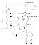
what is an easy way to bias this top half?
I don't need to go for power right? I should aim for low parts count...
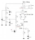
If I run the cascode from the top rail then I could bias the lower tube easily with the plate resistor of the preamp 12ax7. The grid for the el84 colud be biased with batteries rock solid. So no high value cathode resistor and no coupling cap. If the grid stopper resistors were removed and pure silver wire for signal path could I use my tube amp as a linear cb amp? I'm just kidding of course.
SUPERS~1 by Dirtyrottenstinkingbiker, on Flickr
I don't need to go for power right? I should aim for low parts count...
If I run the cascode from the top rail then I could bias the lower tube easily with the plate resistor of the preamp 12ax7. The grid for the el84 colud be biased with batteries rock solid. So no high value cathode resistor and no coupling cap. If the grid stopper resistors were removed and pure silver wire for signal path could I use my tube amp as a linear cb amp? I'm just kidding of course.
An externally hosted image should be here but it was not working when we last tested it.
SUPERS~1 by Dirtyrottenstinkingbiker, on Flickr
Last edited:
I really do have some though, for making colloidal silver... This wire I ordered on ebay for making it.. You use a resistor to limit the current to one miliamp with three or four nine volts connected to each other in series in some hot distilled water for couple hours..You don't need silver wire for CB frequencies! (Or audio)
I just thought it funny to remove the grid stoppers and insert something of less resistance than even copper wire.
Last edited:
It works! I think I can make it better by playing with the bias a little bit but it acomplishes the goals I had in mind, direct coupling, class a2 and cascode output all with low parts count. Any suggestions and comments are welcome 🙂
bias attempt by Dirtyrottenstinkingbiker, on Flickr
An externally hosted image should be here but it was not working when we last tested it.
bias attempt by Dirtyrottenstinkingbiker, on Flickr
Has anybody ever tried this to see what it sounds like? I think it's pretty interesting, especially as a super easy way to drive the top tube into grid current.
Power cascode - Power Cascode
Friend
I made this projects and sound really fine.
Aldovan
- Status
- Not open for further replies.
- Home
- Amplifiers
- Tubes / Valves
- Power tubes in cascode for output section?