Hello
Yes I will rebuild it haw it was originally .
I will try your idea to .
I will replace the 47pF silver mica with 100pF also silver mica .I have at home .
The amplifier does not sound bad at all , I like it , I built several NAIM clone and these are far the best .
Also I will try a bit slower power transistor MJL21194 that is very close to the transistor what Avondale use .
Thanks one more time
Greetings
Hello Andrew
These amplifier very sensitive to capacitor #6 but also sensitive to the decoupling capacitors size.
Before with the old set up I tried 470uF decoupling and it get " muddy" also I tried to use 100uF to replace #6 and almost similar result .
I think I will leave it how it was .
I like that sound "really good" . I will do one more test with a slower power transistor .
Similar speed what Avondale use !
I built 4 or 5 different version of Naim clone these one is so far the best !
My first try I purchased a kit from Ebay , after the McBride clone and so on.
I afraid to do any measurement (the reason I burn done the amp at first time)
I made a short circuit with my DMM when I tried to measure the voltage on the driver transistor .
Thank you for your advise .
Also I will go back to the original value emitter resistor to 0r22
I will let you know if any positive come out from your advise . I try to rebuild it I change one part at the time and I do listening test !
Cheers
Hello
I went back to the original design .It has the best result like that, I get the best sound.
Of course I feet all the parts together to get the best sonic result .
Only problem I have when I turn of the amplifier and the PS loose the voltage around
10Volt the power transistors open up and the offset increase up to 6-7VDC on the speaker terminal .😱
I ask people who built the same amp or similar ad they told I must use a DC detector on the output of amplifier .
All Naim clone need one or there is a built in circuit to avoid the DC go out to the speakers .
I'm not happy about but what can I do now ?😕
I tried a large Philips 4700uF capacitor on the output of the amplifier an it degrade the sound , I can hear it very well .
I think now I will try some DC detector on the output , let see which one has less effect on the sound ..
Thanks for your help and advise guys especially to Andrew .
Cheers
6-7 volts is not a problem unless it is hooked to a tweeter. This amount of signal will not damage a normal woofer.
I know of no handy way to correct the condition but really it does not seem like much of a problem to me. Output caps sound bad as you discovered. Please note the larger electrolytic caps tried have higher leakage current and is probably related to the problems with worse sound.
Did you happen to try the 100pF in place of the 47pF at TR4?
Hello
Sorry Sumaudioguy
I didn't answered to your question , I was busy .I will try to replace the Tr4 with 100pF .
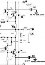
Also I would like to know if is a good idea to use a small 10uF decoupling capacitor on the power transistors how they did on the attached schematic? Or before the two Diode each side ..
The NCC200 has decoupling capacitor not like the Naim 250 or 140 and 180.
These idea I found on the net here .
Modifying Naim Audio power amplifiers
output transistor decoupling caps decouple both+ve and -ve power rails on each board with the highest possible quality caps (eg Rubycon ZL) 470uf, 50V (see fig 8) right next to the output power transistors.
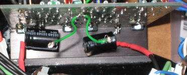
Fig11.
Rubycon ZLs soldered to output transistors under the boards.
(Green wires are where an Evox MMk was removed so you can see). Note on the picture in mod 3, the 4 extra black wires going to star ground for the ZLs. See fig 8 and 9. This was another big mod. I loved it. Just added more power, authority, attack etc blah, imaging, highs, lows whatever.
Martin clark says this is the huge mod on his Nait as per page here as it helps clean up the power rails reducing distortion and is the major bang for buck power amp mod. It probably reduces the rail noise the input has to see when the output transistors suck current but who knows. For a Nap 140 which has rails running at around 34V it is safest to use a 50V cap. Rubycon ZL series give extremely low impedance and are my choice, though Panasonic FM series look very tasty by specs and are cheap. Rubycon ZA series are only rated to 35V so dont use here. going more than 470uf had no benefit according to Martin.
solder capacitors C10 and C11 in fig8 to the correct pin of the output transistors under the boards (solder to the actual pins as the caps must be as close to the transistor as possible) and run flying leads back to the star earth between the main psu reservoir capacitors NOT a 0V point on the actual amp boards. Use at least 1mm2 wire for the OV return wires for a good low impedance connection. You only need to use 2 leads as per fig9 as, as Martin says, 'there is no interaction between pairs of caps sharing a return to the main 0v star point - this is a Class B amp, so only one half of the output stage conducts (and needs decoupling) at a time under load.
Note that on T03 transistors, because of the nature of the actual package, on one rail you will be able to solder directly to one of the pins of the transistor but on the other rail of each board the power goes in via the fixing screws. On this side solder to the nearest available lead (actually the power rail supply pin I think) unless you want to drill holes into the PCB and connect there.
Either way results are an immediately noticeable increase in 'slam' and weight and a general tidying up of the sound- everything just sounds more lifelike.
Out of interest the Avondale NC200 boards do something similar, decoupling the input stage power rail from the output stage with an RC network and diode similar to that of traditional Naim preamp (though Les uses 220ohm/100uf if I remember). Not compared both techniques but would guess the results to be similar. check out the schematic on his website.
Thanks to Martin Clark
What do you think about these ?
Greetings
Sorry Sumaudioguy
I didn't answered to your question , I was busy .I will try to replace the Tr4 with 100pF .
Also I would like to know if is a good idea to use a small 10uF decoupling capacitor on the power transistors how they did on the attached schematic? Or before the two Diode each side ..
The NCC200 has decoupling capacitor not like the Naim 250 or 140 and 180.
These idea I found on the net here .
Modifying Naim Audio power amplifiers
output transistor decoupling caps decouple both+ve and -ve power rails on each board with the highest possible quality caps (eg Rubycon ZL) 470uf, 50V (see fig 8) right next to the output power transistors.
Fig11.
Rubycon ZLs soldered to output transistors under the boards.
(Green wires are where an Evox MMk was removed so you can see). Note on the picture in mod 3, the 4 extra black wires going to star ground for the ZLs. See fig 8 and 9. This was another big mod. I loved it. Just added more power, authority, attack etc blah, imaging, highs, lows whatever.
Martin clark says this is the huge mod on his Nait as per page here as it helps clean up the power rails reducing distortion and is the major bang for buck power amp mod. It probably reduces the rail noise the input has to see when the output transistors suck current but who knows. For a Nap 140 which has rails running at around 34V it is safest to use a 50V cap. Rubycon ZL series give extremely low impedance and are my choice, though Panasonic FM series look very tasty by specs and are cheap. Rubycon ZA series are only rated to 35V so dont use here. going more than 470uf had no benefit according to Martin.
solder capacitors C10 and C11 in fig8 to the correct pin of the output transistors under the boards (solder to the actual pins as the caps must be as close to the transistor as possible) and run flying leads back to the star earth between the main psu reservoir capacitors NOT a 0V point on the actual amp boards. Use at least 1mm2 wire for the OV return wires for a good low impedance connection. You only need to use 2 leads as per fig9 as, as Martin says, 'there is no interaction between pairs of caps sharing a return to the main 0v star point - this is a Class B amp, so only one half of the output stage conducts (and needs decoupling) at a time under load.
Note that on T03 transistors, because of the nature of the actual package, on one rail you will be able to solder directly to one of the pins of the transistor but on the other rail of each board the power goes in via the fixing screws. On this side solder to the nearest available lead (actually the power rail supply pin I think) unless you want to drill holes into the PCB and connect there.
Either way results are an immediately noticeable increase in 'slam' and weight and a general tidying up of the sound- everything just sounds more lifelike.
Out of interest the Avondale NC200 boards do something similar, decoupling the input stage power rail from the output stage with an RC network and diode similar to that of traditional Naim preamp (though Les uses 220ohm/100uf if I remember). Not compared both techniques but would guess the results to be similar. check out the schematic on his website.
Thanks to Martin Clark
What do you think about these ?
Greetings
Attachments
Last edited:
C10 and C11 should be connected to each other using the shortest possible lead lengths and the junction taken to the Speaker return, again using the shortest possible lead length.
I my view the caps provide HF current capacity from the transistor to the speaker and back again through the figure of 8 just created. That 8 must be very short and very compact to perform at HF.
I my view the caps provide HF current capacity from the transistor to the speaker and back again through the figure of 8 just created. That 8 must be very short and very compact to perform at HF.
C10 and C11 have always improved power supply impedance making it lower. These grounds should not go to the speaker ground but back to the star ground as you have written. However the value of 470µF is to large from my testing. More like 100µF is a better choice. The larger the value the more current total and higher current means the inductance of the ground wires causes more drop. I usually attach to the point nearest the driver transistor as is possible and not at the power transistor though it probably makes little difference.
In my 135 watt amp with 8 inches of 14 gauge lead from the main cap a 10kHz wave will cause 4 volts peak drop at the transistors due "parasitic" inductance. Best result of reduced voltage drop were obtained with the 47µF and 100µF values. Larger and smaller values caused more drop than did the optimum value. Further test on many different amplifiers has repeatedly shown this is the correct range of value. Testing on a Bryston 4B showed substantial drop in distortion, -12dB at 20kHz with this simple change.
For input stage decoupling the diode is probably not necessary. The input stage bypass capacitors should be pretty large. The schematic shows 100µF there but I use 1000µF for that location. A large capacitor there could cause turn on problem though so be careful for that. In that location it is good to use a quality high speed cap also. Please notice the input stage has a very wide bandwidth compared to the output stage and needs a power supply which remains low impedance over that wide bandwidth.
Good luck-🙂
- Status
- Not open for further replies.
- Home
- Amplifiers
- Solid State
- Power transitor question