Hello
I would like to know can I use these power transistor with good result on 35mA bias .
http://www.onsemi.com/pub_link/Collateral/MJL4281A-D.PDF
It say Gain Linearity from 100 mA to 5 A
Or better to use some slower transistor like these two
http://www.onsemi.com/pub_link/Collateral/MJL21193-D.PDF
The next option would be these , I have all these 3 devise at hand !
http://www.onsemi.com/pub_link/Collateral/MJL3281A-D.PDF
Someone (Mike B) said the last one tend to have hars sound !
I used before MJL0281A but no longer available .Unfortunately I burnt one side the amplifier .
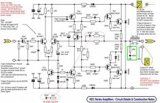
These is the Avondale NCC200 clone amplifier .
Did someone tested these transistors ?
Please let me know .
Greetings !
I would like to know can I use these power transistor with good result on 35mA bias .
http://www.onsemi.com/pub_link/Collateral/MJL4281A-D.PDF
It say Gain Linearity from 100 mA to 5 A
Or better to use some slower transistor like these two
http://www.onsemi.com/pub_link/Collateral/MJL21193-D.PDF
The next option would be these , I have all these 3 devise at hand !
http://www.onsemi.com/pub_link/Collateral/MJL3281A-D.PDF
Someone (Mike B) said the last one tend to have hars sound !
I used before MJL0281A but no longer available .Unfortunately I burnt one side the amplifier .
These is the Avondale NCC200 clone amplifier .
Did someone tested these transistors ?
Please let me know .
Greetings !
Never tested that particular transistor. Topology seems to have a lot more to do with the sound than a specific device. I can use floor sweepings in this one design here and still get great sound and test specs. Not true for some of the other designs. Don't blame the device for a bad result...unless it says TI on it. Been burned by that brand every time used for the last 35 years! Never again.
Hi,
the 4281/4301 are good transistors.
They will work in a ClassAB amplifier.
35mA bias is unusually low for an EF output stage and would require 0r68 emitter resistors for optimum ClassAB bias.
the 4281/4301 are good transistors.
They will work in a ClassAB amplifier.
35mA bias is unusually low for an EF output stage and would require 0r68 emitter resistors for optimum ClassAB bias.
On Avondale's website, they recommend MJ15003 (or BUV20). Why not use one of those? Their datasheets are here: MJ15003 and here: BUV20.
Of those you listed, the slower MJL21194 would be the best match in terms of speed. The NCC200 circuit has some unusual compensation that suggests it might be picky about the speed of the output devices...😕
Of those you listed, the slower MJL21194 would be the best match in terms of speed. The NCC200 circuit has some unusual compensation that suggests it might be picky about the speed of the output devices...😕
HelloI used before MJL0281A but no longer available .Unfortunately I burnt one side the amplifier .
But NJW0281 is available. You replace the MJLs with them.
Sajti
Now at least working and not bad
Hello
I have at hand the MJ15003 but that is in metal case ! Actually I'm not a fan of the MJ13003 device , I'd rather would pick MJ15024 .
Much better after my ear .
My PC board was design to use flat case power transistor .
I replaced the burnt transistor with the faster MJL4281A and I increased the emitter resistor from 0R22 to 0R68 .
Andrew do I need that high value emitter resistor the orig was only 0R22 ?
These amplifier use only NPN transistors on the power stage !A post the schematic so U can see it .
The driver I use MJ15024 , MJ15025 .
The amp burnt because accidentally I made a short circuit with my DMM.
Now the sound is OK but I really can not do a loud test , today Sunday .
I live in a apartment I do not want disturb the people now .
Tomorrow . Probably I will test the slower power transistor to .
Thanks for your help guys.
Greetings
Attachments
But NJW0281 is available. You replace the MJLs with them.
Sajti
I second this suggestion. They are also low-beta droop devices.
Hello
I'm more than satisfied with the MJL4281A thanks to Andrew. It does sound great , even if I would have more MJL0281A I would not go back .
The sound much open than the another side , better transparency , bass is good to .
I will replace the another side to to MJL4281A .
Can I use 54VDC power supp in 8 Ohm .
I will never drive it not even on half volume .
The bigger transformer much better quality,the reason I would like to go from 42V to 54V .
Probably it will be less a bit because 39-0-39V the transformer .
I will lose some percent after the rectification .
I will see , these is a great amp ! I like her a lot .
Greetings
Attachments
post 6 schematic
Hi,
there are a number of component value changes I would experiment with.
Are you interested?
Hi,
there are a number of component value changes I would experiment with.
Are you interested?
Hello Andrew
Of course, if it make my amp sound better or it will be more stable that always is a good think .
The sound now is not bad (actually I like it a lot with these power transistor) but I'm always open to improvement .
mathelaszlo2@yahoo.ca
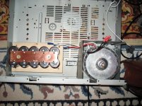
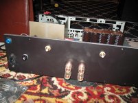
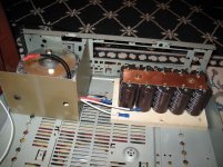
Today I started to put together the power supply , connectors etc . Until now it was built on a piece of plywood , it was easier to replace parts or work with .
Thank you
Greetings
Of course, if it make my amp sound better or it will be more stable that always is a good think .
The sound now is not bad (actually I like it a lot with these power transistor) but I'm always open to improvement .
mathelaszlo2@yahoo.ca
Today I started to put together the power supply , connectors etc . Until now it was built on a piece of plywood , it was easier to replace parts or work with .
Thank you
Greetings
Attachments
Last edited:
Have used a lot of Sanken 2SA1170 and 2SC2774. I know these are old numbers and Sanken has an updated version. Have had great luck with these and they are very linear. FOr drivers I am liking the KSC2690 and its complement. 150mHz and 2 amps with full SOA at 10 watts...maybe if memory is half right.
Vishay has matched pair JFet suitable for inputs.
Vishay has matched pair JFet suitable for inputs.
Hi,
there are a number of component value changes I would experiment with.
Are you interested?
If your interested, one thing I would certainly change is the 22K resistor on the second leg of the LTP. The LTP leg currents should be the same, and the Vce should also be similar. If one has greater Vce than the other, Pd will not be the same so the change in conductance with temperature will not be the same. This will lead to Vout DC drift.
Hello
On the input I tried many different Bipolar like 2N5551 ,BC550C, MPSA6 ,2SC2547, right now I use BC546B .
I can try 2SK170BL , but not always the best choice ...Who knows .
Lets wait on Andrew , He always come up with some great idea .
Of course thank you for your advise to .
Cheers !
On the input I tried many different Bipolar like 2N5551 ,BC550C, MPSA6 ,2SC2547, right now I use BC546B .
I can try 2SK170BL , but not always the best choice ...Who knows .
Lets wait on Andrew , He always come up with some great idea .
Of course thank you for your advise to .
Cheers !
The LTP transistors has different function in here .
All NAIM type schematic use in one leg 1K and on the another leg 22K .
I have at least 5 or 6 different schematic and all has like these !
Here is a another schematic !
http://www.neilmcbride.co.uk/output-amp2.pdf
I built these one to but the NCC200 much better .
Greetings
All NAIM type schematic use in one leg 1K and on the another leg 22K .
I have at least 5 or 6 different schematic and all has like these !
Here is a another schematic !
http://www.neilmcbride.co.uk/output-amp2.pdf
I built these one to but the NCC200 much better .
Greetings
Hello CBS240
I'm not sure if I replace on the LTP the 22K resistor is a good idea .
I did some research and all Naim type amplifiers built like that .
I will wait on some expert guy opinion on these . (I do not say you are not but I don't know you as well like Andrew, nothing personal)
If you read the red notice next to the schematic certainly it has a big impact on the offset .I afraid I will and up with a big offset or worst .
A blew up the amplifier one side accidentally with the DMM (now much better thank to Andrew) I have only one more set power transistor the same hFE .
I need that to the another side .
I wait on Andrew's suggestion , or advise .
I know him a couple years back from the forum , He has some great advise (idea)mostly .
Cheers
Last edited:
Hi,
this NCC schematic has used many unconventional techniques, components and values.
I suspect this makes it sound quite different from a normal set up.
You may like the designer's set up a lot and everything that you change from the design values may sound worse. So beware, these are suggestions for experiment.
47uF (C6) in the NFB. Try 150uF or 220uF. Try adding 1uF PP in parallel.
10uF in the input High Pass filter. Try 4uF or very slightly less.
100uF decoupling. Try 1000uF. Reduce the 220r rail resistors to 100r.
TR4 & 6 are passing 9mA to 10mA and TR7 & 8 are passing 5mA to 6mA.
First decrease the 100r to 51r. Check the bias through the output devices is unchanged, i.e. 0r22 current increases by ~5.5mA.
The 47pF Miller comp may need slight increase.
Measure the voltage at the two emitters of the LTP pair. Measure the difference in voltage between the two emitters.
Measure the voltage at the two collectors and the difference between the collector voltages.
This has been set up to add deliberate distortion and will give the "sound" of this amplifier.
Hello Andrew
I did tried before some of these idea but not all in one time !
When you say First decrease the 100r to 51r. you think about the resistors from the driver emitter to the power transistor emitter .
I just want to be clear on these .
Right now I use 0R68 emitter resistor do I keep that also or go back to the orig 0R22 value ?
I will set up the amplifier after your advise (only one side so I can com pair to the another side )
Thank you very much .
Cheers
0r68 is unusually high for a 1pr output stage.
Check the voltage Vre and work out the current passing across the output.
Check the voltage across the driver emitter resistor VreD. Calculate the current through the driver.
Calculate the current through the output device.
Change ReD from 100r to 51r. Now adjust the bias so that output device bias is the same. The total quiescent current to the amplifier will be higher, about 5.5mA higher. You may find that 30r or even 24r may sound nicer, but only experimentation will determine.
As the driver current increases the driver gain increases. This may require a tiny bit more compensation around the VAS to prevent peaking on fast signals.
Hello Andrew
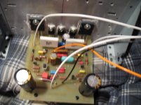
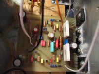
I made all the mod what you suggested . I set up the bias these side of the amp to the same like another side .
I do not like the result .
The sound no longer open (detailed) how it was , it is muddy I don't like at all.
I will leave it one more day to burn in a bit but I don't have much hope to get better .
I did not made any measurement ,voltage or mA , I afraid because that is how I burn the amplifier before with my DMM I made a short circuit .
Just the bias I set up and I check the offset.
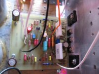
I post two picture from the on side with the new set up and the old side also , you can see the difference between the two side .
Cheers
I made all the mod what you suggested . I set up the bias these side of the amp to the same like another side .
I do not like the result .
The sound no longer open (detailed) how it was , it is muddy I don't like at all.
I will leave it one more day to burn in a bit but I don't have much hope to get better .
I did not made any measurement ,voltage or mA , I afraid because that is how I burn the amplifier before with my DMM I made a short circuit .
Just the bias I set up and I check the offset.
I post two picture from the on side with the new set up and the old side also , you can see the difference between the two side .
Cheers
Attachments
What you got would be pretty much what I would expect. The 50 puts to much current to the output from the drive transistor on the top. With quasicomp circuit a lot of drive to the transistor directly from the driver is needed. Remember quasicomp does not work without feedback. Voltage source on top and current source on the bottom output stage. The Mission Cyrus 2 was the best of the quasicomp amps I ever heard.
If you are feeling brave there is one thing you may wish to try- change the 47pF silver mica at TR4 to a value like 100pF. That may be to much though. Maybe a 75pF there. Just a suggestion though.
If you are feeling brave there is one thing you may wish to try- change the 47pF silver mica at TR4 to a value like 100pF. That may be to much though. Maybe a 75pF there. Just a suggestion though.
- Status
- Not open for further replies.
- Home
- Amplifiers
- Solid State
- Power transitor question