Renton76,
For your picture in Post # 17, You might put the choke to the right of where the rectifier tube is, and move the rectifier tube to where the choke was.
More space from choke to output transformers.
Unless you are using a very large first capacitor in a cap input filter, the hum that is induced in the choke from the power transformer field, will be far less than the hum from the first capacitor ripple that goes to the choke.
Last edited:
Hey,
thanks for this great support.
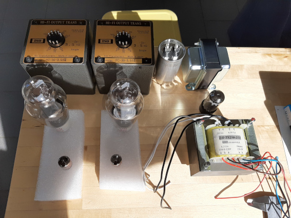
The first cap of CLC will be around 30 to 47 uf. The motor run capacitor in the picture is the 2nd and comes after the choke.
I did a mistake, by aligning the choke. It´s in the following picture in its best postiton with the OPTs.
As the choke´s end bells leave space for an iron isolating sheet of 1mm, it think, I`m gonna insert one to shield the laminations.
Do you think there´ll be trouble with the orientation of the ptx and the choke (4 inches space inbetween), or shall I let the ptx´s lamination axis radiate to the tubes?
)(
thanks for this great support.
The first cap of CLC will be around 30 to 47 uf. The motor run capacitor in the picture is the 2nd and comes after the choke.
I did a mistake, by aligning the choke. It´s in the following picture in its best postiton with the OPTs.
As the choke´s end bells leave space for an iron isolating sheet of 1mm, it think, I`m gonna insert one to shield the laminations.
Do you think there´ll be trouble with the orientation of the ptx and the choke (4 inches space inbetween), or shall I let the ptx´s lamination axis radiate to the tubes?
)(
An externally hosted image should be here but it was not working when we last tested it.
Last edited:
It's hard to know how to align power transformers etc because the OPT's are potted.The only way to properly align the various tfmr's is after it's built .If you encounter a problem with noise it might be possible to rotate the OPT's without disrupting your wiring too much.
I´ve contacted ISO. They say the optimal (90 degree position) of the opts and the choke are like the last foto uploaded.
My prob is the p2p build and and a cnc top plate. once milled, ... .
My prob is the p2p build and and a cnc top plate. once milled, ... .
Last edited:
Hi, I like to jump in and ask about my project.
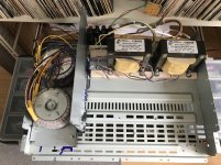
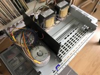
I have 2 toroidal power transformers with electrostatic shields positioned behind the metal shield and 90 degrees from the output transformers.
Behind them is metal back plate ( not in picture ) closing them fully in isolation.
Do you think it would be enough distance/shielding to minimize influence from them in the enclosed enclosure?
Attachments
Personally I do not find shielding necessary as a detrimental property to audible benefits. It's just a good idea to have it if needed.
Shielding or split bobbin is far more important for specific measurement instruments IMHO.
There was a client who had an oscillation within his amplifier and got it tamed by disconnecting his shield.
My personal power transformers of my system do not have ES shielding. Other mechanical factors play much more significance in the audibility in power transformers.
Probably yes. Probably no. But I view from a pragmatic point a view. It's the client's job, not mine. Problem is a vague word.
The modern common DIYer doesn't have much time for problem solving. It's a species seeking having quick and simple fun.
The modern common DIYer doesn't have much time for problem solving. It's a species seeking having quick and simple fun.
When not connected to PE, so a user error, and an oscillation occurs (which is not a vague word but a problem) the tech could try to advise the client instead of pulling the silly act of disconnecting the shield.
When it is a technical problem of the amplifier the tech could try to solve it instead of disconnecting the shield. This makes disconnecting the shield a strange solution in both cases.
When it is a technical problem of the amplifier the tech could try to solve it instead of disconnecting the shield. This makes disconnecting the shield a strange solution in both cases.
Last edited:
renton76,
1. The best relative angular orientation of the output transformers and choke can be found by putting 6.3VAC across the choke; and then connecting a scope input, 2nd amplifier and speaker, or headphones/earbud across the output transformer 16 Ohm and Common connections.
You can change the distance, change the rotation, etc. and note the amount of hum.
Then do the same test with 6.3V across the choke, and connect the power transformer 6.3V filament winding to the scope input, input of the amplifier/speaker, or headphones/earbuds. Listen for hum, versus orientation and spacing.
Caution: be sure to insulate all the other windings of the Power transformer.
2. I believe that an Iron or Magnetic Steel plate "Shield" will conduct more magnetic energy from one object to another than it will shield one object from the other. Just my opinion (and my experience when I tried to isolate an interstage auto-transformer phase splitter from other magnetic fields).
3. 30 or 47uF first cap, choke, then a motor run cap? I hope you will use more capacitance for that 2nd cap, or bass frequencies will make the B+ have "Signal Ripple" voltage. Use a stiffer, higher capacitance cap, to filter the output stages B+, either a direct B+ filter cap, or the ultra-path cap.
You do not want the output stage B+ to vary along with the stand-up bass, electric bass, or kick drum, etc. Even though the Average current of an SE amp is relatively steady, the Peak current during a 40Hz electric bass will cause the B+ to Move and Drop (A 120Hz full wave filter cap, is not good enough to filter a 40Hz bass note).
Last edited:
Thanks for feedback Jean-Paul & 6A3!
As I made decision to house the tube amp in old receiver enclosure as a experiment, I'll post my findings once is operational🙂
As I made decision to house the tube amp in old receiver enclosure as a experiment, I'll post my findings once is operational🙂
Hey folks,
many thanks for all the info.
6A3summer: I´m gonna try it out. But it will take some time. Yes, I´m gonna use more capacitance for c2. It´ll be around 250 uf.
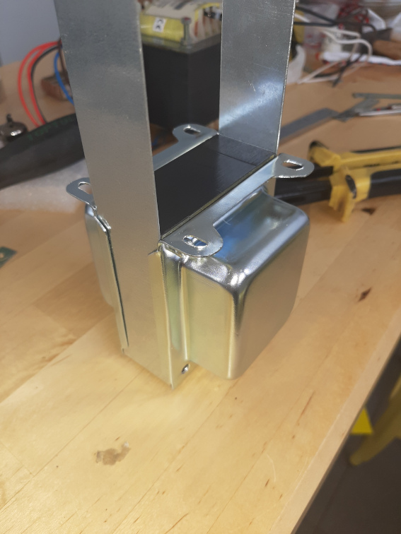
Today I´ve played a bit with my choke. Unfortunately you can´t get special Ei84 end bells for an urpright standing core. So I had ordered one for an EI86 and filled the 1mm gap on each side with an u-shaped steel sheet. Will It produce probs due to eventually shorted laminations? If yes, I´m gonna put some isolation tape on.
many thanks for all the info.
6A3summer: I´m gonna try it out. But it will take some time. Yes, I´m gonna use more capacitance for c2. It´ll be around 250 uf.
Today I´ve played a bit with my choke. Unfortunately you can´t get special Ei84 end bells for an urpright standing core. So I had ordered one for an EI86 and filled the 1mm gap on each side with an u-shaped steel sheet. Will It produce probs due to eventually shorted laminations? If yes, I´m gonna put some isolation tape on.
An externally hosted image should be here but it was not working when we last tested it.
Last edited:
- Home
- Amplifiers
- Tubes / Valves
- Power transformer with no electrostatical shielding. Issue?