Hello forum,
today a custom made power tx for a Tublelab SE was delivered.
I use AE Europe nomally, which generally provide an electrostatic shielding between the primary and secondary windings.
This time I ordered at an other manufacturer who didn't implement a shielding.
The contruction is primary, than b+, than heater windings.
Will that cause an issue or will the amp be fine?
Hope you can help.
Many thanks
Rents
Made a mistake.
The tranny uses a split bobbin.
Primary and B+ on one side. Heater windings on the other.
The tranny uses a split bobbin.
Primary and B+ on one side. Heater windings on the other.
In a mains transformer an electrostatic screen helps with the safety factor in case of fire you could live without that but it helps in low voltage secondaries by acting as an RF filter induced via the mains supply.
It depends how free from interference your mains supply is but yes its not really essential in a good mains supply or you could make up or buy a mains filter.
Split bobbin ?-- lower capacitance but higher leakage inductance .
It depends how free from interference your mains supply is but yes its not really essential in a good mains supply or you could make up or buy a mains filter.
Split bobbin ?-- lower capacitance but higher leakage inductance .
Last edited:
A split bobbin gives very high rejection above about 400Hz.
If you did not specify a (possibly unnecessary) screen then the winder did not do wrong.
If you did not specify a (possibly unnecessary) screen then the winder did not do wrong.
Thank you for the help.
So the electrostatic shielding is unnecessary?
It's not about the winder. I'm asking myself, if I made a mistake.
So the electrostatic shielding is unnecessary?
It's not about the winder. I'm asking myself, if I made a mistake.
Commutation noise, caused by the rectifiers' di/dt in the HV secondary, is the largest noise source in any but the most pathological cases. So, isolating the heater windings from the HV windings is the second best choice. The best choice is to snub the HV windings, and also isolate them from the heater windings.
You didn't make a mistake, you got lucky.
All good fortune,
Chris
You didn't make a mistake, you got lucky.
All good fortune,
Chris
So Chris,
as you wanted. Here I am, holding my freak flag high. 🙂
Hey Chris,
thanks for reply on my transformer thread.
I took a closer look at my tranny and the bobbin is not split. The winding order is primary, b+, and heater windings on the outside.
Do you think, there will be negative audible effects due to the missing shield?
My system is a high resolution one and I wanted ro build my last amp. Therefore really good components like ISO OPTs on my bench.
All I'm afraid of is possibly degrading the sound without knowing.
Many thanks again
Rents
A regular ol' amplifier, made with a mains AC powered transformer with HV and heater windings, has a built-in noise source much bigger than any (non-pathological) external noise source.
The AC to DC conversion makes big (can't be eliminated, but can be minimized) abrupt changes in current through the power transformers' secondary windings, di/dt. These abrupt current changes generate voltage spikes, and that's how spark plugs get sparky.
All rectifiers do it, although some are squishier and cause very slightly less di/dt and some, like vacuum rectifiers, have very low capacitance, so don't couple the spikes into B+ near as much. It's still coupled into the heater supply, so there's that.
But the solution is to snub the reactive parallel circuit of the power transformer's secondary windings' leakage inductance and stray circuit capacitances with a series'd R and C, exactly like a Zobel network. Morgan Jones wrote the definitive and groundbreaking article on the subject in _Linear Audio_ #5. Mark Johnson later refined this to a critical damping model, but I'm not at all sure I'm ready to believe its assumptions. Read and decide for yourself. There's an article in _LA_ #10 and a thread here on DIYaudio:Simple, no-math transformer snubber using Quasimodo test-jig
The older I get, the more I believe in snubbing. It's probably genetic.
All good fortune,
Chris
Last edited:
There will be less rectifier noise on the B+ secondary winding that could possibly transfer to the filament, bias, or other windings, if you use a choke input filter.
But . . . you already have the transformer, and probably the B+ secondary voltage was picked to work with a cap input filter.
(Too late now)
Using a choke input filter, the B+ would be reduced by aproxomately
1/(1.414 x 1/0.9)= 1/(1.414 x 1.111) = 1/1.57 = 0.636
The B+ would only be about 63.6% when using a choke input filter, versus a cap input filter.
In a 50/60Hz power xfmr setting, the leakage inductance works in your favor by providing high pass filtering of the AC line, since it appears as a series inductance with the load. Split bobbin xfmrs work well in small signal settings because of that.
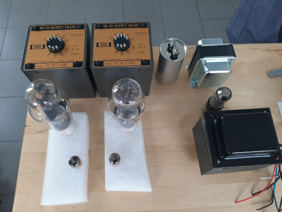
Just wanted to start my Tubelab SE p2p build this week and purchased two ISO opts. I asked the manufacturer which orientation of my Edis power tx would be best using this foto:

ISO´s answer came really fast but was in its second part a bit astonishing. The short version:
Cheap power transformer without electromagnetic shielding. They wouldn`t use it with the FC30s opts and they recommend a better one with shieldings.
I shall strongly think about purchasing a better ptx in respect to the high quality of the ISO opts.
Now I´m confused again. 😉😀😉 Could you please enlighten me. Got the choke and the ptx from Edis. It´s a well known manufacturer and a set of ISO coke and tranny would need additional 560 Euros. Not little money. And I suspect if it would better anything.
Could you please enlighten me? 😉😉
Last edited:
You can buy copper tape and wind it around the power transformer. But it's not even necessary. The pt you have is fine. 
No shield needed, just make sure the tfmr is as far away from the inputs/1st gain stage as poss and make sure it is orientated 90 degrees in relation to the OPT's.
Thanks Bas and Dia,
had this rough transformer layout in mind. There shouldn´t be an issue.
What do you think. Space input tube to ptx is arount 15 cm but will be reduced a bit.
had this rough transformer layout in mind. There shouldn´t be an issue.
What do you think. Space input tube to ptx is arount 15 cm but will be reduced a bit.
An externally hosted image should be here but it was not working when we last tested it.
Looks ok, I can see your thinking - mains tfmr, rectifier, choke, main cap, that's good. If you made the RCA inputs top mounted, bottom left, that'd work.
One other thing to think of too is heater wiring placement,which in this case would be to jam the wiring into the chassis corner and run it up the RHS, then over to the OP valves.
One other thing to think of too is heater wiring placement,which in this case would be to jam the wiring into the chassis corner and run it up the RHS, then over to the OP valves.
Cheap power transformer without electromagnetic shielding. They wouldn`t use it with the FC30s opts and they recommend a better one with shieldings.
I find electrostatic shielding to be mildly beneficial and audible, based on transformers which have it.
Never experimented much with electromagnetic shielding as i believe in distance and proper orientation. And external PS.
Anecdotally, the worst sounding PS choke i have ever used was a shielded Tango. Of course, it may have sounded bad for reasons other than shielding.
I get less than 100 uV (< 0.1 mV) hum on most of my amplifier designs.
None of my amplifiers have a copper tape shield around the transformers (not on Power Transformer, Choke, Output Transformers).
But the distance from magnetic device to magnetic device, and relative rotational orientation are Paramount.
I pay very good attention to creating very short individual ground loops, instead of serial grounds, etc.
A star ground without first having short local ground loops that then connect to the star, often does not work well.
* Input stage local ground loop, incluing RCA jacks that are insulated from the chassis
* B+ center tap to first cap negative local ground loop
* Etc.
Then connect those local loops to the star ground.
The worst amplifier hum I get is about 1mV or 2 mV . . . Because the amplifier has a Magnetic Steel Chassis.
The only solution to that problem is changing to an Aluminum Chassis.
Just my experience and just my opinions.
Last edited:
- Home
- Amplifiers
- Tubes / Valves
- Power transformer with no electrostatical shielding. Issue?