Hello all:
I've embarked on my first serious mission of constructing a SE tube amplifier and I'm running into a few dilemmas. With time and deliberation I could probably figure them out, but being stuck inside with little to do, my ambition's getting a bit feverish.
My configuration that I'm attempting to use is a 6550 at 300V driven by an E88CC in an ultra low-gain setup at 80V (I planned everything out so that the 6550s would be driven to full power by around a volt of input at the preamp stage). The output transformer that I've planned on using is the GXSE10-2.5K.
The PT transformer that I've been looking at is the Edcor XPWR221, but I'm worried about using it for a few reasons:
1. The 250-0-250 rating of the 221 is close to what I need for the 6550, but I need to use a resistive voltage divider to bring it down closer to 300. I also decided to use another resistive voltage divider on the B+ line to load the E88CC. Both of these voltage dividers run between the B+ line and ground. The way I'm doing this scares me a bit, as I am not sure if the voltage divider lines will load the power transformer too much or even if my methodology is sound in the first place. Would I simply use high-rating resistors to prevent excessive current, or is there a better way to step the voltage down that I'm not aware of?
2. I've planned for this to be an easy college amplifier to go with a pair of R-51Ms, which means I'd be running current through two channels. Does that mean that I'd have to cut channel current down to at most 65 mA (as the 221 is rated for 130 mA)?
For the 6550 I've set the bias to -15 V, and according to my load lines the max current draw is ((B+) - bias) / (transformer resistance) = (285/2500) = 114 mA. Now the load lines say that the quiescent plate current is roughly 130 mA. For the E88CCs (running at 80V with roughly 5000 ohm load), the max plate current is about 15 mA. Adding those together brings 129 mA, which is very close to the power transformer's max current rating. Factor in the voltage dividers and the second channel and we're talking way over 130 mA (...right?). Meaning the transformer will probably die.
Given that I'm doing all of the math right (I am not trained to do this, just a high school senior that's bored and that's read all the safety precautions), I'm going to need a pretty meaty transformer, or I'm going to have to change a lot of things about this amp. Now, maniacs, what can you tell me?
Welcome.
Fine figuring for a HS student, but..... what is it supposed to DO? I see many part-numbers, but the only performance spec is "driven to full power by around a volt of input". No output? 5 Watts? 20 Watts? Does it even matter?
What Vg2 and plate current have you figured for this 6550? (There's no factory suggestion for 300V, so I assume you have been plotting.)
If parts are not bought yet, _I_ would suggest a stereo "Champ". 6V6 is a sweet tube, adaptable to many modes, a LOT cheaper than 6550 has become, and a hard-played Champ (or Epi Valve Jr, same with EL84) will usually annoy the neighbors. The iron to beat a 6V6 past conservative ratings is readily available and affordable as Fender Replacement for Champ (OT) and DeLuxe (PT).
If the Edcor transformer is specified at AC current it will not be possible to get more than roughly half of that as DC current, (my old books say a factor of 1.6 between AC and DC current but it is better to use a factor of 2). If this is the case you would need a much bigger transformer.
BTW, you don't need a resistive divider to reduce voltage to the input tubes, the current is constant so a simple dropping resistor is OK.
BTW, you don't need a resistive divider to reduce voltage to the input tubes, the current is constant so a simple dropping resistor is OK.
Last edited:
The above posts are good, but I'll add a little more.
If you have 300V of B+ and you want 80V on the plate of the 6922, and say maybe you will run 4mA through the tube, that's a 55K plate load. You definitely don't need to run a ton of current through the driver tube.
You are triode wiring the 6550 hopefully. That will make the project far less frustrating.
Hello all:
For the E88CCs (running at 80V with roughly 5000 ohm load), the max plate current is about 15 mA. Adding those together brings 129 mA,
If you have 300V of B+ and you want 80V on the plate of the 6922, and say maybe you will run 4mA through the tube, that's a 55K plate load. You definitely don't need to run a ton of current through the driver tube.
You are triode wiring the 6550 hopefully. That will make the project far less frustrating.
You don't need to waste current with voltage dividers - class A stages draw constant current (on average) so a series resistor and filter capacitor will do. As for current rating, center tapped transformers are rated for DC current, which is essentially the same as RMS current in each half. So 60 mA would be your max idle current for stereo, 18W at 300V, well within 6550 rating. EL34 or 6LCGC would do as well, at lower cost.
You've gotten a lot of general good advice so far from us 'maniacs'. Here are a few things that'll make your project go more smoothly, without changing the fundamental “goodness” of the 6550 design.
[1] Use vacuum rectifier AC → DC conversion.
[2] Don't worry about the voltage on the 6550. You can always change bias-point to keep it working within maximum plate dissipation limits.
[3] Run the ECC88 at higher plate voltage. Easy, since the B+ supply is not a low-volgate design.
[4] Don't worry too much about gain — If it turns out to be too weenie for you, there are plenty of ways to spark it up.
[5] Also, don't run the ECC88 at 15 mA. Shoot more conservatıve, around 3 - 5 mA.
[6] I didn't get an impression whether this was to be Class-A style push-pull, or just single ended. Maybe I read too fast. My eyesight is really ebbing these days.
[7] Consider looking up one of KodaBMX's designs of the last year. They are really impeccable, and don't use heart-attack-high-priced parts. Seriously…
Anyway, all that and … let's start seeing your schematics, good fellow.
BTW… I too started designing in earnest … in high school. Was considered quite the odd-nerd, for that. However, I cobbled together an amplifier for the Soph-Hop that gave me legendary status, remembered today. 1,000 W, in an era when 100 W was huge. The gymnasium rocked. Cheap. So, you go, lad.
Best of Luck
⋅-=≡ GoatGuy ✓ ≡=-⋅
________________________________________
NOTES
[1] … because it offers slow-turn-on high voltage supply, automagically. Also, also essentially free of the flyback-ringing effect that designers have to work around with silicon rectification.
[2] … because 6550's are designed to nominally handle all sorts of abuse.
[3] … A little less gain, but more linearity.
[4] … you can always add another stage. Indeed… if I were you, I'd just cut out an extra hole for a socket. Install the socket. Don't wire it up. It'll come in handy for Version 2.
[5] … Along with hotter anode, of course.
[6] … just asking
[7] … He and I have talked quite a bit about his balanced, optimal cost designs. They're quite good.
> I didn't get an impression whether this was to be Class-A style push-pull, or just single ended.
Says "SE" first sentence.
OK, I'm back-figuring. 350V raw will be say 320 on tube. 42 Watts at 320V is 0.13A. 320V at 0.13A is 2,430 Ohms which fits a 2.5k OT. On thumbs it figures as 16 Watts audio. From experience it needs very careful tweaking to get over 13W. And it is HOT. And mono.
And then we have "a pair of R-51Ms". So the goal is two channels. Real HOT. Or cut each back to half current. Meaning double OT impedance. And 42W 6550s are not needed, even a 6L6 could loaf. 8W audio per channel. Which is not a lot softer than 5 Watts, and 6V6 at 350V B+ and 5k load will do sweet and cheep.
I appreciate the compliments, but my designs are only suitable for push pull operation due to there being no gap in the OPT.
That said, it's not hard to use a CCS or resistor for current balance if you don't mind wasting power, but at the point you could add a couple of tubes and have much more power.
That said, it's not hard to use a CCS or resistor for current balance if you don't mind wasting power, but at the point you could add a couple of tubes and have much more power.
Thanks for all the replies, I really do appreciate the help.
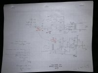
I've attached my schematic. Don't freak about the non-standard resistor and capacitor values (estimation comes later!).
I think I'm going to take baudouin0's advice and run the 6550 at 350 V of B+. Won't take me but a few minutes to redraw the load-lines and reconfigure everything, as this schematic definitely could use another look. I realize that I configured the E88CCs to give me very little distortion on the positives and a ton of distortion on the negatives, so I think that I'm going to increase the plate load (per audiowize) and flatten out the load line to get a more linear result. If I increase the load to 10000 Ohms and bring the plate voltage to 100 V, we're talking 10 mA for max plate draw and 5 mA for quiescent current (which is hot, but I want to keep the bias there because, as I said, I'd like to be able to drive the amp with something small like an iPod--drivers can take a bit of hot bias too, from what I've heard). 5 mA at a volt dropped (signal) keeps me at a 200 Ohm cathode resistor.
Per GoatGuy's advice for vacuum tube rectification, I'd like to get into that at one point in my life, but right now as a "broke" high school student I'm going to make do with silicon rectification 😉.
I'll reconfigure the E88CCs to give me a gain that matches the bias of the 6550 at 350 V.
I guess my main point of confusion resides in what qualifies as current draw for the amp. Would it simply be the supplied voltage divided by the sum of all resistors/impedances throughout the power path (i.e. 354/(OT impedance + all resistors))? I'd assume it'd be that since tubes don't pull the DC current from the power line through their bodies.
If I'm getting 65 mA to the circuit for one channel, that's 37.5 mA for two, so I may end up doubling the OT impedance if I want to keep it stereo. The boys at diyaudio were right when they said power supplies were not something to skimp out on...
Based on my calculations I was milking about 14 W from the output stage. It's okay, I'm not shooting for 1000 W, though that would be super nice. For now I'll keep myself satisfied with that beautiful EL6471 schematic.
Thanks again. Keep it going!
Attachments
Last edited:
Nothing wrong with solid state rectifiers, other than a higher voltage compared to tube rectifiers.
When heated (cathode) the tube will start conducting when B+ is available, so you do have DC current through the tube!
Regards, Gerrit
When heated (cathode) the tube will start conducting when B+ is available, so you do have DC current through the tube!
Regards, Gerrit
Your schematic shows a connection to the control grid, g1.
It also has a 'suppressor grid' connected to the cathode (actually sheet metal beam formers).
It does not show any connection for the screen grid, g2.
If it is to be triode wired, it should have a 100 Ohm resistor from g2 to the plate.
If it is beam power wired, the screen, g2, needs to go to a series dropping resistor from B+, and connect a capacitor to g2, and the other end of the cap to ground.
Attached Hammond guidelines for transformer sizing.
Better still is to model the power supply in PSU Designer II by Duncan Munro (free) since large capacitors, low resisitance in transformer can have a large impact on the peak currents.
Do not oversize your capacitors, the current sizing fad has gone to the ridiculous.
IIRC there were some postings by IIRC Eli Duttman on "hash filtering". Big capacitors results in spikes well into the RF region and it is audible and hard to get rid off. Besides under chassis chokes are not that expensive and the reduced costs of smaller capacitors help to pay for the choke.
E.g. I'm building a small SE 6BQ5 amplifier and the two finals draw about 100mA together but I need a 260mA transformer without a choke in bridge rectification and about 200mA with a 5H choke. With same sized capcitors ripple goes down from 220mV with a resistor to 15mV with a choke.
If you are a college student I would suggest to look at a 6BQ5 since these tubes are a lot cheaper and the transformers required are a lot smaller. Heck, you can get cheap Russian 6P14P equivalents instead of the 6BQ5 and I have not hear a bad sounding 6BQ5 amp. (But built a SE 6L6GC and was not impressed besides weighing something like 18 Kg and costing a small fortune with James transformers). Spend more money to get more efficient speakers instead of making a bigger amplifier.
E.G.:
I once had the LS5/12A and two monoblocks with each 4 x KT88 pushing out some humoungous amounts of power. Yet the Klipshorn Scale is 23.5 dB more efficient than the LS5/12A.
In other words the LS5/12A would need to be driven with 895 Watts to get the same level of output as the Klipshorn Scala with a 4 watt SE amplifier. Unfortunately the LS5/12A can only handle 150 Watts so it cannot even go as loud as the Klipshorn.
But... the Klipshorn won't fit next to my desktop computer.
Attachments
Last edited:
I guess my main point of confusion resides in what qualifies as current draw for the amp. Would it simply be the supplied voltage divided by the sum of all resistors/impedances throughout the power path (i.e. 354/(OT impedance + all resistors))? I'd assume it'd be that since tubes don't pull the DC current from the power line through their bodies.
I'am not sure what you are trying to say here. The OPT has a DC resistance which is much lower than the AC impedance which is basically the speaker impedance x turns ratio ^ 2. The DC resistance is just the coil resistance. Most of your current draw will be the DC current through the 6550's the rest will be small. In class 'A' the average current draw does not change with signal level. The tube draw current from the cathode to the plate. So when calculating plate voltage its the DC resistance of the OPT to use. The AC impedance needs to match roughly the plate resistance so you get maximum AC power transfer and hence maximum output power for your bias point (somebody correct me as that's not quite correct).
I'am not sure what you are trying to say here. The OPT has a DC resistance which is much lower than the AC impedance which is basically the speaker impedance x turns ratio ^ 2. The DC resistance is just the coil resistance. Most of your current draw will be the DC current through the 6550's the rest will be small. In class 'A' the average current draw does not change with signal level. The tube draw current from the cathode to the plate. So when calculating plate voltage its the DC resistance of the OPT to use. The AC impedance needs to match roughly the plate resistance so you get maximum AC power transfer and hence maximum output power for your bias point (somebody correct me as that's not quite correct).
Last edited:
aenima1983,
In your schematic in your post # 10 . . .
What are the output tube screens, g2 connected to?
In your schematic in your post # 10 . . .
What are the output tube screens, g2 connected to?
Figured out the current draw thing, had to consult the girlfriend's dad about it. He got a kick out of that
Updated schematic:
I connected g2 to the plate via a 100 Ohm resistor for triode mode. I will go about determining the value for the feedback resistor once I've got more experience with testing tube tech. I'd like to be able to hear changes.
Thanks for the tips once again!
P.S. Amadeus, I shall try out those tubes
Attachments

I'd recommend Antek for your power transformer. Much cheaper than Edcor, and better performance, not to mention delivery and Quality Control.
BTW, I was in an exchange on the Edcor support forum several years ago, where Brian Weston himself pointed out that the Edcor PTs amp rating is for continuous duty. Essentially, the amp rating is for the secondary being loaded 100% of the time. Since they are center-tapped and as such would be wired with two diodes and CT grounded, each half of the secondary has a 50% duty cycle, meaning the actual AC amp rating (if wired as described) is 2X the stated. So, using the XPWR221 as an example, you can safely load it to (2X 130mA) 260mA AC when rectifying as described. Bridge rectified, it would be a different story.
Hammond using DC rating is even further into the weeds if you ask me. I wish Edcor and Hammond would adhere to the industry standard nomenclature with VA ratings and none of this wouldn't be such a guessing game.
Hammond rates their coils in VA too. The VA rating includes ALL windings though.
I stopped buying Hammond a long time ago. Last time I saw one it had DC amp rating for the HT.
Schematic in post # 16:
Your negative feedback resistor from the output transformer secondary is connected to ground at the input tube cathode.
You need another resistor between the self bias resistor and bypass cap network, and ground.
That way, the negative feedback develops a voltage across that added resistor, and that negative feedback voltage is applied to the parallel of the self bias resistor and bypass cap (which means the negative feedback voltage can drive through the bypass cap to the cathode).
A 50 Ohm resistor will not affect the input tube bias much, but the 100k negative feedback will have to be much lower than that.
You also need to ground the bottom of the output transformer secondary winding (that makes the negative feedback voltage have a reference to work against . . . ground).
Floating won't work, and also can make the amp unsafe.
Change your 6550 15k g1 resistor to 47k, and change the coupling cap to that resistor to 0.2uF (use a modern 600V part, keep leakage very low).
That LED across 6.3VAC (8.9V peak) needs a series resistor, or it will flash on once, and then go off forevermore.
The order of connections to the primary and the secondary will determine whether you have negative feedback; or whether you have positive feedback and a powerful oscillator.
You may have to adjust the 7.5k resistor, it will only have 30V across it.
Likewise, 63.4K is way too much for the last resistor in the B+ filter, you will not get enough voltage to the input stage's plate resistor.
The E88CC is an RF tube, you need a grid stopper between the volume control wiper and the input triode grid, use 1k with it connected directly at the socket tab.
Because you are using the 6550 in Triode wired mode, then depending on the output transformer primary impedance, and your loudspeakers, you may find that no negative feedback, is as good as or better than with negative feedback.
All in all, that is a great project.
Happy listening.
Last edited:
- Home
- Amplifiers
- Tubes / Valves
- Power Transformer Troubles