The article appears to be more a 'heads up' not to gloss over a few consequences of using vintage transformers meant for vintage applications.
The topic of not using a valve diode heater winding is relevant, in that some may well relate a reduction in 10-15VA of secondary load as 10-15W of additional load power that can now be extracted from the B+ supply. And others may relate the 10-15VA as watts lost in the transformer.
A general rule of thumb is that 10-15VA of transformer will only generate about 5-7W of rectified and cap filtered output, due to poor power factor of rectifier with cap input. Staying with the heater winding as the application, one should only expect to rectify and filter and power about 5-7W of heater with DC, as compared to a 5V 2A or 3A diode heater with AC. If you tried to get 10-15W DC out of the heater winding, the rms current in the winding would be more, and so the loss in the winding would be higher - causing stress higher than designed for.
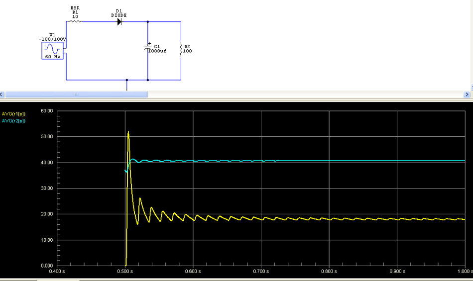
Luckily one can use simulation (eg. PSUD2) nowadays to calculate and compare winding rms current levels for different diodes, filters and loads, and hence get a reasonable idea of whether the new application is more stressful than original specs.
The topic of not using a valve diode heater winding is relevant, in that some may well relate a reduction in 10-15VA of secondary load as 10-15W of additional load power that can now be extracted from the B+ supply. And others may relate the 10-15VA as watts lost in the transformer.
A general rule of thumb is that 10-15VA of transformer will only generate about 5-7W of rectified and cap filtered output, due to poor power factor of rectifier with cap input. Staying with the heater winding as the application, one should only expect to rectify and filter and power about 5-7W of heater with DC, as compared to a 5V 2A or 3A diode heater with AC. If you tried to get 10-15W DC out of the heater winding, the rms current in the winding would be more, and so the loss in the winding would be higher - causing stress higher than designed for.
Luckily one can use simulation (eg. PSUD2) nowadays to calculate and compare winding rms current levels for different diodes, filters and loads, and hence get a reasonable idea of whether the new application is more stressful than original specs.
Last edited:
the paper overlooks the biggest problem.
a lot of vintage transformers were designed for a 115 Volt line.
now it's common to see a almost 125 Volt line.
(it'd mid-afternoon, freezing rain and my line is 124.4V)
a lot of vintage transformers were designed for a 115 Volt line.
now it's common to see a almost 125 Volt line.
(it'd mid-afternoon, freezing rain and my line is 124.4V)
a lot of vintage transformers were designed for a 115 Volt line.
now it's common to see a almost 125 Volt line.]
Yup, in the USA.
As rayma points out, permanent high line voltage is a problem in the US, whereas other countries typically don't have that concern, although a recent modern concern is that domestic solar PV systems can cause daytime increases for some.
Luckily it was not uncommon for vintage transformers to have some primary winding taps, especially if the transformer was for international sales or a country that had known variations - in Australia we often had vintage transformer primaries with 230, 240, 250V taps (and/or 0, 10V on the other end).
Although a secondary level stress, that article didn't describe transformer in-rush and how that may change. Rectifier tube heaters incur a secondary side inrush that may well be 5x their VA level (so typically 50-75VA instant loading on the secondary side) and ramp down over a second or more. B+ supply typically won't induce turn-on in-rush, and if a 'hot' turn-on does occur then the B+ inrush is subdued due the valve diode resistance and the typically constrained amount of first filter capacitance.
In contrast, ss diodes incur a much higher inrush VA over a shorter time frame of a few mains cycles, especially due to the use of much higher initial filter capacitor levels. The effective peak VA draw may reach say 400V by a few amps for a moderate valve amp with 100uF or more first filter. That could incur quite a mechanical shock for vintage windings and insulation.
ours was 220 volts, today 240 volts ac is common...
transients die down in 5 to 6 cycles, so 6/60 seconds or 6/50 seconds....
not so much an issue with tube rectifiers since tube heaters take about 10 secs to warm up...
transients die down in 5 to 6 cycles, so 6/60 seconds or 6/50 seconds....
not so much an issue with tube rectifiers since tube heaters take about 10 secs to warm up...
Last edited:
Solid state amplifiers draw much less power at idle than at full power, so the heating effects are only an issue at high power levels - the windings are very adequately sized for normal operation and handle inrush current easily, and most of the time for domestic use the transformers run cool.
Valve amps present a pretty constant load on the transformer, so typically will run warm/hot in normal operation as this is much closer to the max load. Thus the headroom is less. Changing to semiconductor diodes will increase the I2R losses as per the article - there's a parameter called conduction angle, the proportion of the cycle for which the diodes conduct, which can be very small for semiconductor diodes unless extra resistance and/or inductance is added to increase conduction angle.
Windings in a transformer (or any other inductive device with steel laminations) feel very little force. Most of the force is transmitted direct to the core itself, so mechanical strain isn't a great issue. However vibrating windings may abrade each other long term, one of the reasons transformer windings are routinely impregnated with lacquer (as well as better heat conduction, excluding moisture, etc etc).
[ Early in the development of electric motors windings were on the surface of the magnetic circuit, and did experience large forces, till it was discovered/realized than burying the windings in slots transferred the forces direct to the steel as well as allowing much smaller magnetic gap, and motors got a whole lot more powerful and robust. Transformers can be thought of as windings buried in a slot, perhaps, but gain the same desirable property of mechanical forces being mainly transfered to the strongest part of the device. ]
- Home
- Amplifiers
- Power Supplies
- Power transformer stress