I hear something quite often that I don't fully understand. It seems many people believe that having a transformer that is rated much above what is being drawn is somehow hard on components like voltage regulators or even diodes or tubes. I am not talking voltage I am tanking the amp/Ma rating.
I understand that a few more volts may be available to the different taps on a tube transformer but other than that is there any reason for concern?
I sold McIntosh equipment back in the day and you could run those amps night and day for weeks and transformers never got hot. Some modern stuff has iron that gets quite toasty.
I have built SS stuff with over rated transformers without a problem and some stuff stays on 24/7.
I am building my first tube amp and I already bought a pretty robust Power Transformer. See below for what is available and what the amp uses.
H.V. tap amp uses 90Ma - 300 available
6.3 volt uses 3.6 amp - 7 Amp available
5 volt uses 3 Amp - 5 Amp available
Should I be OK?
An oversized transformer will run cooler. It won't sag with a heavy load, so voltages will never drop. It might have a massive inrush current upon power up, which might be what people are worried about. Needs a big primary fuse and fat power switch.
Also, if the PT is supplying a tube rectifier, a certain minimum resistance is required to limit the peak ripple current. If the PT has 'too low' a secondary resistance, additional resistor(s) have to be included.
To answer both I intend to use two high amp Carling switches. I intend to add resistance the center tap to ground to help out the 5U4G. Not a ton of resistance ( 150 ohms). CLC filter after the rectifier.
Modeled on PSUD adding 15 volts to allow for line voltage and oversize transformer the numbers come right in line. 45 output tubes. TSE (tubelab single ended)
from Tubelab | Dedicated to advancing the state of the art in affordable high end audio.
Modeled on PSUD adding 15 volts to allow for line voltage and oversize transformer the numbers come right in line. 45 output tubes. TSE (tubelab single ended)
from Tubelab | Dedicated to advancing the state of the art in affordable high end audio.
The diodes become hot mainly because of the charging current of the first cap which is usually 3 times the load current and according to Schuler's book it can reach up to 8. This is why an oversized transformer can be beneficial and also can withstand the high transients of an amp. Furthermore it's more quiet i.e. no buz and never gets hot, as you said.
A transformer in the range of 500VA and above will need an NTC or some other soft-start implementation, whether it is toroidal or EI. Otherwise you will have big start-up currents that will pass into the audio and the transformer itself will have a hard time, sometimes one can see sparks inside the coils, sometimes the core can be magnetized heavily. And it's getting worst when the mains curve is near the p-p at the time of switching, I suspect.
An over-rated fuse is not going to protect the device when it's really needed, better to use slow-blow types.
Last edited:
To answer both I intend to use two high amp Carling switches. of the art in affordable high end audio.[/url]
No need for this. Just add a disk cap, say 1500V across the contacts of an ordinary switch. A spark usually comes out from the switch when shutting down , generated from the inductance of the circuit.
The diodes become hot mainly because of the charging current of the first cap which is usually 3 times the load current and according to Schuler's book it can reach up to 8. This is why an oversized transformer can be beneficial and also can withstand the high transients of an amp. Furthermore it's more quiet i.e. no buz and never gets hot, as you said.
A transformer in the range of 500VA and above will need an NTC or some other soft-start implementation, whether it is toroidal or EI. Otherwise you will have big start-up currents that will pass into the audio and the transformer itself will have a hard time, sometimes one can see sparks inside the coils, sometimes the core can be magnetized heavily. And it's getting worst when the mains curve is near the p-p at the time of switching, I suspect.
An over-rated fuse is not going to protect the device when it's really needed, better to use slow-blow types.
Well… there's a whole bag of disinformation!
[1] Diodes take their hardest 'moment of service' when the power is turned on. It turns out however they always are tasked with dissipating the same amount of energy during that turn-on surge. How much? Exactly equal to the full charge of the front-end capacitors average voltage plus the energy of the down-wind caps. Its math.
A larger transformer will have lower effective series resistance, and thus higher peak current capacity. This shortens the time over which the energy developed and/or needs to be dissipated. It is for these reasons that the general recommendation is to use modest current impeding series resistors, AND to limit that initial first set of capacitor reservoir farads.
[2] The '3×' or '8×' business again depends a lot on the size of the capacitor relative to the demand for its reservoir of power down-wind. And yes, the series resistance of the secondary windings. And so much more. But “napkin estimates” of 3× to 8× are fine. Some say 5×, and be done with it on the average.
[3] But “This is why an oversized transformer can be beneficial” … is a canard, my good fellow. Nothing of the sort is actually true: averaged out over the entire sinusoidal power cycle, whether it is “3×” or “8×”, the duty cycle of the pulses counters the peak. The average current flow is nearly constant, for nearly constant current delivery to the amplifier.
[4] … “to withstand the high transients of an amp”. Which is exactly false. The whole point of a power supply is to decouple the downwind power demands (transient or smooth) from the power supply. And vice versa! It works both ways, you know.
[5] … “furthermore there's no buzz and never gets hot” … are independent concepts. Hot is hot because the power delivery and transformer losses heat it. Buzz is buzz, and it depends on how the transformer is wound, how it is potted, and how it is mounted.
[6] … “Transfomer 500+VA needs an NTC/soft-start implementation, whether torroidal or EI” … mmm, it is not the transformer that needs soft start. It can be argued that the DIODES or RECTIFIER TUBES need the soft start, to offer the poor things lower peak startup current. Or to stretch out the charging of all those capacitors. But it isn't the transformer that needs the 'break'.
[7] … “Otherwise big startup currents will pass into the audio (section)” Ummm… again, no: All those capacitors and resistor/inductors (and especially if you use 'em, regulators) will be doing a fine job to keep said transients out of the amplifier's audio section. Sorry… for tube systems, its even 'nicer behaved', in that the valves take several seconds to turn on. Far longer than the charge-up time of the power supply. By the time they do, things are quite settled down, regardless of the oversize of the power transformer.
[8] … “And the transformer will have a hard time… sparks … heavily magnetized” Remarkably, again, no. If one ever sees 'sparks' in a power transformer, it is time to get it out of there, and replace it. The sparks are not caused by capacitor surge-current charging. They're caused by insulation breakdown. The 'magnetization' thing is also a nasty little myth: the core-steel used is specifically engineered to not permanently magnetize in any particular direction. Moreover, should it be some totally out-of-spec soft iron material, the subsquent 50 / 60 Hz power within a few seconds will restore its 'permanent' magnetization to a nominally indistinguishable from normal value.
[9] … “And it's getting worst when the mains curve is near the p-p at the time of switching, I suspect. ” … well, on this one we agree - which is why another poster recommended using heavy duty power mains switches. The one thing that you will get at an ever higher amount is inrush current when the power is switched on during a power peak. Hard on switches. Hard on the rectifiers if they're solid state. And all that is rendered way less harmful when a modest-sized wire-wound power resistor is added in series to each of the transformer secondary 'hot' leads. Using 2 of them (for a 2-rectifier full-wave section) is preferable to using one on the center tap, as they're going to be tasked with commutating only ½ the total average power. Run cooler. Etc.
[10] ... slow blow fuses: be careful with this recommendation! You can do as much damage with modestly overrated slow-blow fuses as you can with 'normal ones' that are overrated to take the initial surge.
Sorry to tear apart your comment … but I just get tired of reading myths. This industry is already totally packed full of snake oil, myths, innuendo and balderdash. We must try to get rid of at least some of it.
GoatGuy
Last edited:
No need for this. Just add a disk cap, say 1500V across the contacts of an ordinary switch. A spark usually comes out from the switch when shutting down , generated from the inductance of the circuit.
Ah… and then you move the spark from coming from the flyback current of the transformer being turned off … to the capacitor that's nominally building up (and losing) charges when the switch is off (open). When it closes whatever joules of energy in that capacitor go directly into the switch contacts. Ouch! Moreover, having a capacitor there may not seem harmful when the device is off, but in reality it acts as a series impedance to the amplifier, letting a continuos low level of leakage thru. In many ways, it would be better to recommend a series R+C so that the R takes the sudden-discharge energy dissipation instead of the switch contacts. It also doubles as 'taking half the energy' of a suddenly turned off inductor flyback current, instead of it all dumping into the capacitor.
Just saying.
GoatGuy
A larger transformer will have lower effective series resistance, and thus higher peak current capacity. This shortens the time over which the energy developed and/or needs to be dissipated. It is for these reasons that the general recommendation is to use modest current impeding series resistors, AND to limit that initial first set of capacitor reservoir farads.
Goat Guy,
I am using 5u4G rectifier with 20uF first cap 7Henry choke and 160uF on the H.V. tap.
My transformer has 30 Ohm resistance and the RCA data sheet says I am ok with that.
My voltage is good with these numbers (275 Volts) modeled on PSUD
What is considered modest current impeding resistors. If I go too high voltage will drop below 275. Lookes like I could add 20-30 ohms and still be alright.
That's about right. 30 to 50 Ω each, would be my guess. Don't worry too much whether you run at 275 volts or 265 volts or even 250 volts. There's a relatively broad range of “sweet spot” you can adjust simply by changing the bias on the output tubes. They're often just as happy at slightly lower voltages (and 250 is 'only' 10% below 275)…
Your system will work just fine.
GoatGuy
Your system will work just fine.
GoatGuy
Waltroman, that should be adequate, you are drawing 1/3 of the rated power at idle.
if the amp is biased at class A, that may be all it will ever draw.
I had to use a 120 VA torriod in my amp as it would easily fit. I just upped the reservoir caps to 22,000 uf. this provides unclipped power of 55 w/ ch class AB and 150w class D to sub. It Will sag significantly driving sine wave signals to those levels as opposed to music.
Amp draws 12 watts at idle from wall Transformer runs cold.
Well… there's a whole bag of disinformation!
[1] Diodes take their hardest 'moment of service' when the power is turned on. It turns out however they always are tasked with dissipating the same amount of energy during that turn-on surge. How much? Exactly equal to the full charge of the front-end capacitors average voltage plus the energy of the down-wind caps. Its math.
A larger transformer will have lower effective series resistance, and thus higher peak current capacity. This shortens the time over which the energy developed and/or needs to be dissipated. It is for these reasons that the general recommendation is to use modest current impeding series resistors, AND to limit that initial first set of capacitor reservoir farads.
[2] The '3×' or '8×' business again depends a lot on the size of the capacitor relative to the demand for its reservoir of power down-wind. And yes, the series resistance of the secondary windings. And so much more. But “napkin estimates” of 3× to 8× are fine. Some say 5×, and be done with it on the average.
[3] But “This is why an oversized transformer can be beneficial” … is a canard, my good fellow. Nothing of the sort is actually true: averaged out over the entire sinusoidal power cycle, whether it is “3×” or “8×”, the duty cycle of the pulses counters the peak. The average current flow is nearly constant, for nearly constant current delivery to the amplifier.
[4] … “to withstand the high transients of an amp”. Which is exactly false. The whole point of a power supply is to decouple the downwind power demands (transient or smooth) from the power supply. And vice versa! It works both ways, you know.
[5] … “furthermore there's no buzz and never gets hot” … are independent concepts. Hot is hot because the power delivery and transformer losses heat it. Buzz is buzz, and it depends on how the transformer is wound, how it is potted, and how it is mounted.
[6] … “Transfomer 500+VA needs an NTC/soft-start implementation, whether torroidal or EI” … mmm, it is not the transformer that needs soft start. It can be argued that the DIODES or RECTIFIER TUBES need the soft start, to offer the poor things lower peak startup current. Or to stretch out the charging of all those capacitors. But it isn't the transformer that needs the 'break'.
[7] … “Otherwise big startup currents will pass into the audio (section)” Ummm… again, no: All those capacitors and resistor/inductors (and especially if you use 'em, regulators) will be doing a fine job to keep said transients out of the amplifier's audio section. Sorry… for tube systems, its even 'nicer behaved', in that the valves take several seconds to turn on. Far longer than the charge-up time of the power supply. By the time they do, things are quite settled down, regardless of the oversize of the power transformer.
[8] … “And the transformer will have a hard time… sparks … heavily magnetized” Remarkably, again, no. If one ever sees 'sparks' in a power transformer, it is time to get it out of there, and replace it. The sparks are not caused by capacitor surge-current charging. They're caused by insulation breakdown. The 'magnetization' thing is also a nasty little myth: the core-steel used is specifically engineered to not permanently magnetize in any particular direction. Moreover, should it be some totally out-of-spec soft iron material, the subsquent 50 / 60 Hz power within a few seconds will restore its 'permanent' magnetization to a nominally indistinguishable from normal value.
[9] … “And it's getting worst when the mains curve is near the p-p at the time of switching, I suspect. ” … well, on this one we agree - which is why another poster recommended using heavy duty power mains switches. The one thing that you will get at an ever higher amount is inrush current when the power is switched on during a power peak. Hard on switches. Hard on the rectifiers if they're solid state. And all that is rendered way less harmful when a modest-sized wire-wound power resistor is added in series to each of the transformer secondary 'hot' leads. Using 2 of them (for a 2-rectifier full-wave section) is preferable to using one on the center tap, as they're going to be tasked with commutating only ½ the total average power. Run cooler. Etc.
[10] ... slow blow fuses: be careful with this recommendation! You can do as much damage with modestly overrated slow-blow fuses as you can with 'normal ones' that are overrated to take the initial surge.
Sorry to tear apart your comment … but I just get tired of reading myths. This industry is already totally packed full of snake oil, myths, innuendo and balderdash. We must try to get rid of at least some of it.
GoatGuy
Thanks for your comments. Usually I don't like to pass around something that I haven't experienced my self.
1. It has to do with the ratio of Vpeak to Vaverage. A starving capacitor will charge during the initial cycle demanding heavy currents and after this, it goes as described by the ratio above, which actually tells us everything we need to know. And the diodes are switched on, only for a small fraction of cycle and only then are getting hot.
2. Same as previous.
3. When the rms secondary current is much greater than the dc current, the conduction angle is small. A big reservoir cap in conjunction with a high secondary resistance will add heat to the PT.
4. Maybe in a perfect world. A heavy transient can be really.. heavy. According to M.Jones, a pair of large amps with generous caps could easily draw 60A pulses of current from the mains.
5. I don't see where our disagreement lies. And yes, you can hear buz when the PT is overloaded.
6. I am afraid that the transformer comes also into play when it is big enough. We all know what happens with big toroids when start up.
7. DH rectifiers need less than a second or so to light up and the 5U4G is one of them. I can assure you that the rising energetic yield is quite audible, even with 87dB speakers.
8. Not magnetized. You are right. But the sparks can come out only during start up, somehow leaving the PT undamaged if you are lucky, but not for too long.
10. No. Heavy transients again. Slow blow, but not overrated.
PS Would you like a myth to make you happy? Slow-blows are better for audio!😀
a bigger traffo will have more surface area with which to get rid of the heat,
but temperature rise of traffos has more to do with the chosen flux by the designer
more than anything else...
since i make my own traffos used in my tube builds, these are what i
have come to like:
1. full wave bridge psu's has better traffo utilization than the traditional FWCT,
since in a FWB, the secondary windings run currents for the full 360* of input power waveform..
2. full wave voltage doublers, lower voltage secondaries making high voltage B+ possible,
making traffos is very easy and insulation requirements in traffos are not so stringent..
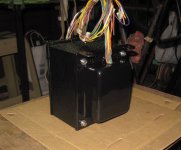
the traffo shown below is a 1 3/4 inch center leg stacked to 3 inches....
but temperature rise of traffos has more to do with the chosen flux by the designer
more than anything else...
since i make my own traffos used in my tube builds, these are what i
have come to like:
1. full wave bridge psu's has better traffo utilization than the traditional FWCT,
since in a FWB, the secondary windings run currents for the full 360* of input power waveform..
2. full wave voltage doublers, lower voltage secondaries making high voltage B+ possible,
making traffos is very easy and insulation requirements in traffos are not so stringent..
the traffo shown below is a 1 3/4 inch center leg stacked to 3 inches....
Attachments
If you are worried about sparking at the switch, add an X-rated cap across the transformer primary. It needs to be X-rated for safety. It needs to be across the primary (not the switch) for long cap life and to guarantee that 'Off' really means Off.
A common misconception of newbies (and some others who should know better) is that a high current source (whether DC or AC) can somehow force extra current into something which does not require it and cannot handle it. This implies that they still don't really understand the difference between voltage and current. Such people should really not be working with high power electronics, for their own safety.
A common misconception of newbies (and some others who should know better) is that a high current source (whether DC or AC) can somehow force extra current into something which does not require it and cannot handle it. This implies that they still don't really understand the difference between voltage and current. Such people should really not be working with high power electronics, for their own safety.
If you are worried about sparking at the switch, add an X-rated cap across the transformer primary. It needs to be X-rated for safety. It needs to be across the primary (not the switch) for long cap life and to guarantee that 'Off' really means Off.
A common misconception of newbies (and some others who should know better) is that a high current source (whether DC or AC) can somehow force extra current into something which does not require it and cannot handle it. .
Hi,
1. An X2 rated capacitor is usually across the transformer primary to lower the supply impedance at higher frequencies and so to compensate RFI/EMI. This is why it stacked in the end of the line, preferably soldered on the transformer's pins. It might help when a surge is circulating the line but it doesn't offer any substantial protection to the switch. One should still add a dumber across the contacts and have the switch bypassed from surge, thus protecting the contacts from surface oxidation.
2. You can not just use a high impedance source as an act of preventing failure of underrated and/or insufficient components. This is fundamentally wrong. We have always to apply Ohm's law.
Cheers!
A cap across the primary protects the switch just as well as a cap across the switch. This is because the primary source of inductance in the circuit loop being broken by the switch is the transformer, so the cap kills the back emf at source.Alkis said:An X2 rated capacitor is usually across the transformer primary to lower the supply impedance at higher frequencies and so to compensate RFI/EMI. This is why it stacked in the end of the line, preferably soldered on the transformer's pins. It might help when a surge is circulating the line but it doesn't offer any substantial protection to the switch. One should still add a dumber across the contacts and have the switch bypassed from surge, thus protecting the contacts from surface oxidation.
- Status
- Not open for further replies.
- Home
- Amplifiers
- Power Supplies
- Power Transformer Rating Mythology?