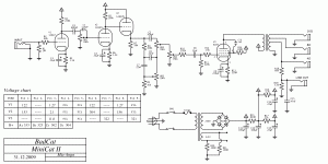
Alright so I have a PT with a 275 VAC output. The Power supply in the schematic I am building has an output of 235 VAC. What is the best way to step this voltage down after the bridge rectifier? I don't think the design will operate the way I want it to with the same set up.
Is there an easy way to change this?
The 4 B+ voltages I need are 333, 323, 302, and 304...
Thanks
Is there an easy way to change this?
The 4 B+ voltages I need are 333, 323, 302, and 304...
Thanks
Is this in regard to the questions you are asking regarding a guitar amp on several other threads?
If so, might I suggest keeping your questions in the same thread if they are referring to a single project or design, that way people know what you are specifically referring to.
There will be several answers to your question. Some that come to mind:
an extra RC network - drops more volts and gives better smoothing.
using a tube rectifier, 5AR4 will drop some volts and give a slow turn on.
use a smaller input capacitor, model in PSUDII
use a voltage regulator, but I suspect this is for a guitar amp and probably not desirable.
In any case PSUDII is very helpful. Read the help file for putting in correct information to get accurate results.
I have used PSUD 2 before and its great, but I was still having trouble getting the voltages I needed and it does not support a parallel option, such as in the design attached.
The attached schematic shows the power supply with a 230V with the proper voltages. I have 275V one.
The attached schematic shows the power supply with a 230V with the proper voltages. I have 275V one.
Attachments
PSUD 2 doesn't do parallel, but that doesn't matter. Just model one side and use appropriately valued current sinks placed after C12 (whole draw of B) and C13 (draw of D only).
Then model, trying Chrish's suggestions, decrease value of C11, increased value of R15, or just throw in another RC filter. You can also try adding 2 equal resistors to each of the PS secondary leads. You model this in PSUD 2 by adding the values of ONE of the two resistors to the PS resistance value.
Then model, trying Chrish's suggestions, decrease value of C11, increased value of R15, or just throw in another RC filter. You can also try adding 2 equal resistors to each of the PS secondary leads. You model this in PSUD 2 by adding the values of ONE of the two resistors to the PS resistance value.
I found a 10H choke that when I put into the power supply, it brings the voltages down significantly, which is much better than what it was before. It appears that this is the way to go, otherwise the tubes are biased way out of where I want them to be.
But to be honest, I may just exhange my PT since its within the 30 days.
But to be honest, I may just exhange my PT since its within the 30 days.
Last edited:
- Status
- Not open for further replies.
