Hello everyone.
I'm building my first large power transformer.
By "large", I mean bigger than 100 VA.
I'm using a split bobbin, but there're three secondary windings.
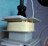
So I decided to add an electrostatic shield between primary and one of the secondaries (which go together on one side).
I used a strip of adhesive copper foil, with a wire soldered on one end, and the other one just half a centimeter appart from making a complete loop. Is it OK?
I'm building my first large power transformer.
By "large", I mean bigger than 100 VA.
I'm using a split bobbin, but there're three secondary windings.
So I decided to add an electrostatic shield between primary and one of the secondaries (which go together on one side).
I used a strip of adhesive copper foil, with a wire soldered on one end, and the other one just half a centimeter appart from making a complete loop. Is it OK?
Attachments
You've completely defeated the advantages of a split bobbin for creepage and isolation !
The primary copper seems small proportionally. or I wonder if the oversized copper on all the secondaries pushed your XFMR design over the edge, so to speak. Did you ever find out the max VA's for your core size?
The primary copper seems small proportionally. or I wonder if the oversized copper on all the secondaries pushed your XFMR design over the edge, so to speak. Did you ever find out the max VA's for your core size?
Last edited:
You've completely defeated the advantages of a split bobbin for creepage and isolation !
I know, but this is the bobbin I have for this stack size.
It is a 150 VA for tube amplifier. One of the secondaries is high voltage, and bigger than the primary.
There will be some bobbin height left, but not as much as you might think.
The question is, is the electrostatic shield a valid one? Will it work?
Would it be OK if the copper foil ends touch each other?
I know that many people just lay a single layer of wire and connect only one end to ground (and it is important to not connect the other end). But it is easier for me to do like this.
No. The ends need to overlap, but with isolating material in between.Would it be OK if the copper foil ends touch each other?
Best regards!
I know, but this is the bobbin I have for this stack size..
I like split bobbins, I think they provide superior isolation over an electrostatic shield for low to mid-band. My point being is you should use it properly E.g. keep the secondaries only on one side.
Electrostatic shields are often a waste of effort with a poor overall (system)grounding /measurement plan. what is yours ?
Your primary should fill the first window.
All your secondaries should fill the second window.
Sure. But I have only limited variety of wire and bobbins.
Also, all secondaries won't fit in this core/stack.
This design is the best I could come out with.
If it works fine, then that's ok for me at this point
")
More and better will follow
link
Maybe this will work....... Homo ludens electronicus
look under
Tutorials and other stuff
Hi,
Try this google homoludens transformers
The link went 404 when I tried to put it up here
Lots of good reads on this site.
I built my first transformer from this information !
Have fun I do !
Merry Christmas !
NS
Maybe this will work....... Homo ludens electronicus
look under
Tutorials and other stuff
Last edited:
The shield can have a few purposes.
As this is a power transformer, and as you are bypassing the benefit of a split core, then the shield can become an extra safety mechanism by becoming a 'protective earth' barrier between primary and secondary (as required in some standards) - but that requires the shield and lead to be rated for earth fault current level (ie. the earth wire size that would be acceptable for the primary winding current rating/wire size).
For an electrostatic screen, then just one screen is corner cutting, as it forces capacitive currents from the primary side, and from the secondary side, to pass along the same leadout wire, and connect to the same grounding point. If you are wanting to route those currents to different parts of the equipment then you need two screens.
Capacitive currents are by nature higher in frequency, and so the screen should be designed with high frequency current flow in mind. That is better achieved by locating the lead-out wire in the 'middle' of the turn, and by using a layout that minimises the length of the lead-out wire.
shielding
That's great!
I built a M2 I have never built a shield for a signal transformer,I did notice the pins on the side are too long and would touch anything wrapped around the sides so I clipped them off for clearence,So I have some MU steal ,do I just make a box with a top,does it need a ground to the board or soldered all around?
NS
Mod if this should be in M2 thread please move it.
Yes, very interesting page. I already knew about it, and I also recommend it!
That's great!
I built a M2 I have never built a shield for a signal transformer,I did notice the pins on the side are too long and would touch anything wrapped around the sides so I clipped them off for clearence,So I have some MU steal ,do I just make a box with a top,does it need a ground to the board or soldered all around?
NS
Mod if this should be in M2 thread please move it.
Last edited:
I'm just using my first PT on a custom made SE KT88 !
It works as expected.
Filament voltage went a bit higher (7V unloaded) so I use a simple 2W 0.22ohm in series and get 6.35V with tubes.
Just the transformer buzzes.
Laminations are just hold together with four bolts. I plan on using yoke or even bells for vertical mounting. I've got bells for lay down, but I thinks that not an optimum choise because of EMI inside the (steel) chassis. Also tightly isolate one more turn with a thick isulation.
I don't plan impregnating the transformer. Too much mees for doing at home.
Any reccomend?
- Status
- This old topic is closed. If you want to reopen this topic, contact a moderator using the "Report Post" button.
- Home
- Amplifiers
- Power Supplies
- Power transformer. Is this OK for electrostatic shield?