Folks:
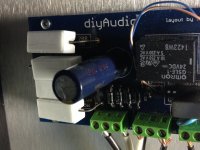
I thought you might find this interesting. This SoftStart board came out of an F5T V2 stereo amp. I'm not sure what the cause of the failure was but one lead on each of the four power resistors was blown out of its hole and one of the four power resistors is fried (the others appear fine). The transformer is a 1kw toroid with 24V secondaries and the power supply has 160kuF in capacitance. I was using 75R power resistors as recommended by AndrewT in this thread (as opposed to the 150 to 180R values in the BOM) and a 4A slow blow fuse.
Do you suggest I increase the resistance on R15-R18, lower the value of the fuse or try something else?
Regards,
Scott
most likely a wrong connection had the full 120 volt line on those resistors, that is the only reason i can think of to cause those resistors to get fried....
check you wiring and you can use a light bulb in series with the mains so that you don't waste parts needlessly.....
19r (75/4) for a 115Vac 1000VA primary sounds about right.
This should allow reliable starting using a T10A fuse.
You might even get away with slightly lower.
The burnt resistors are most likely due to the relay failing to bypass in the 200ms to 300ms required for a soft start.
I have already posted re the lack of a proper timer in this project and the fact that it is direct to Mains powered.
Folks:
I should have mentioned that the SoftStart board was thoroughly tested, turned on and off several times under load and worked perfectly for at least 3 hours, during which time I began slowly raising the current to the MOSFETs. About 3 hours in, I set the current to .9A per MOSFET, put the cover on the amp and walked away. When I checked on the amp 90 minutes later, the SoftStart board had blown and the amp had cooled down.
Further thoughts?
Regards,
Scott
This still sounds like the relay had not bypassed the current limiting resistors.
The timer should bypass in 200ms to 300ms. It will even work well as a soft start with the timer set to 100ms.
The timer should bypass in 200ms to 300ms. It will even work well as a soft start with the timer set to 100ms.
AndrewT:
This is the third SoftStart board I've put into an F5T; all three use the same parts. The first two SoftStart boards were installed in my V3 monoblocks (also with a 1kw toroid and 160kuF in ps capacitance) and they haven't failed yet. Curious...
Regards,
Scott
This is the third SoftStart board I've put into an F5T; all three use the same parts. The first two SoftStart boards were installed in my V3 monoblocks (also with a 1kw toroid and 160kuF in ps capacitance) and they haven't failed yet. Curious...
Regards,
Scott
Can you hear the relay clicking to bypass mode soon after start up?
Can you estimate the time delay?
Can you determine if the relay does actually bypass, after hearing the click?
Can you estimate the time delay?
Can you determine if the relay does actually bypass, after hearing the click?
AndrewT:
Until it failed, the SoftStart board worked fine. The relay would trigger less than a second after the power button was pressed (if I had to guess, perhaps .6 or .7 of a second), and the board was working. As I had noted, I was in the process of adjusting the F5T's MOSFETs when the board blew.
Regards,
Scott
I can't offer any other explanation.
This is especially so since you have confirmed that two similar have worked properly.
This is especially so since you have confirmed that two similar have worked properly.
AndrewT:
I've gone silent on this because we've been hit with a massive ice storm. The power's been out for 4 days so far and we're not expecting it to be restored for another day or two, though snow is also predicted and that may screw things up further. Assuming the pipes haven't burst (a very real possibility), I'll provide further information sometime next week. Otherwise, I'll be offline for an extended period.
Regards,
Scott
I'm surprised you're on line at all.
Hope you get sorted very quickly.
I was snow bound for 7days last year, but the power stayed ON all the way through.
Hope you get sorted very quickly.
I was snow bound for 7days last year, but the power stayed ON all the way through.
AndrewT & Co.:
The ice storm has passed and I've returned from a two week business trip. As noted in another thread (see #2988 in http://www.diyaudio.com/forums/pass-labs/207103-f5-turbo-builders-thread-150.html), I set this amp aside and tried dialing-in a second F5T V2 stereo amp with similar (smelly) results. 6L6 and others have suggested that I verify that the leads extending below the softstart boards are trimmed. I will do so (thought they weren't bad before), and also add to the height of the standoffs to ensure the boards aren't arcing to the chassis, but does this seem like a likely fix? Both of the failed softstart boards worked properly for several hours before the power resistors blew up. I will also offset the power resistors from each other to allow for better cooling on the four long sides, but these minor tweaks seem like an uneducated patch. If you have any further thoughts, I'd be grateful for the advice.
Here's a photo of the second blown softstart board. The photo doesn't do the power resistors justice: there's a crack running the length of each one and nice brown toasting at the ends.
Regards,
Scott
Attachments
Scott, now might be the time to become extra-skeptical. The "I'm from Missouri, you have to prove it to me" kind of skeptical.
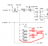
Maybe there is a mismatch between {the PCB layout} and {the relay you purchased}. Maybe your board does not start-soft-then-run-hard. Maybe your board accidentally implements start-hard-then-run-soft. One way to quickly check this with full skepticism, is diagrammed below.
You tack-solder three small components in point-to-point air wiring style, across the top of one of the power resistors. The LEDs light up whenever Softness is engaged. The LEDs go dark whenever HardOperation occurs.
Putting it another way: Whenever destructive power is applied to the 5W resistors, the LEDs light up. So you can carefully watch to see when the resistors are in danger, and when they are not. Remaining skeptical the whole time.
Expected behavior of a good board: When you flip the power switch on, the LEDs glow for just 0.2 seconds, then they extinguish and never illuminate again.
Behavior of a faulty board: When you flip the power switch on, the LEDs glow continuously and never extinguish. (Destructive power is continuously applied to the 5W resistors).
Using two LEDs back-to-back allows them to operate from AC rather than DC. Each diode protects the other from excess reverse voltage.
Edit: the 1200 ohm resistor needs to be rated for 1 watt. Shoulda mentioned that earlier.
Attachments
Last edited:
Mark:
Fantastic -- even a dope like me can do that! I'll report back the results once I've had a chance to replace the power resistors and wire things up again.
Thank you,
Scott
Fantastic -- even a dope like me can do that! I'll report back the results once I've had a chance to replace the power resistors and wire things up again.
Thank you,
Scott
Scott, I made an error in calculating the value of the LED current-limiting resistor in post # 132. I didn't plan for the ugliest worst-case.
Clearly there is enough voltage across each 180 ohm, 5W resistor, to burn them out. Let's make a conservative overestimate of voltage, and then size the LED current-limit resistor to survive even in this worst case scenario.
Assume the voltage across each 180 ohm, 5W resistor so large, that each resistor is being asked to dissipate 25 watts instead of 5 watts (making them go kaboom!). This turns out to be 67 volts across each resistor { math: (67^2 / 180) = 25 watts }
The LED + current limiter sees this same voltage, 67 volts. If we choose LED current to be 8 mA in this case, its current limit resistor value should be (67 / 0.008) = 8400 ohms. The power dissipated in this resistor is (67 * 0.008) = 0.55 watts. So we need an 8.2Kohm, 2W resistor in series with the LEDs.
burnt "series" resistors indicates the relays failed to close,
since closing the relay effectively shorts out those resistors.....
another scenario i can think of, your line voltage dipped
so that the 24volt relay contacts opened...
you can try a 12 volt relay instead....
or you can increase the value of C9 from 1ufd to 2ufd
or you can decrease the value of R14 from 1meg to say 750k...
these mods are designed to increase current to the relay
to a point that it is never de-energized on low ac line voltage dips...
Perhaps the PCB layout and the physical relay do not agree about which is the NC terminal and which is the NO terminal.burnt "series" resistors indicates the relays failed to close,
since closing the relay effectively shorts out those resistors.....
NC: Normally Closed
NO: Normally Open
Mark:
One point of clarification: I've used four 75R five watt power resistors per softstart board, per AndrewT's advice. The LED resistor will naturally need to be adjusted accordingly.
AJT:
I can add a capacitor in parallel with C9; I had used .33uF caps but also have .56uF caps on hand. Could the "low" capacitance (within the range specified in the BOM) have caused the boards to blow?
Regards,
Scott
those caps pass current along with the resistor,
lower than 1 ufd and less current,
higher than 1ufd means more current
the resistor in parallel has a reverse effect.
your problem was the result of your using a 0.33ufd instead of 1ufd....
the combined parallel cap and resistor determined the current to the relay...
let's do some quick and dirty math...
at a line voltage 120v, current with a 1 meg resistor is 120 uA, not enough for the relay.
so the 1ufd cap supplies around 47mA of current, so the capacitor here is critical,
and the reason for that is, a resistor passing the same current will be huge,
probably a 20 watter for reasonable heat, a capacitor does not dissipate heat otoh...
this last option that i favor, a small isolation transformer 120volt primary to 27volt secondary at 200ma
in place of the resistor capacitor combo, will give you more peace of mind, this is how i do mine btw...
You must establish whether the relay is actually bypassing the soft start resistors.
BUT be Careful. You are at mains voltage.
I posted a warning a long while back that the DIYaudio soft start board did not have a proper timer. It uses a very voltage intolerant RC as it's delay. Low voltage can and will prevent the relay bypassing the resistors, particularly if there is a stack up of tolerances that makes the voltage even lower than expected.
I lost a lot of sympathy from the Forum because I dared to criticise the lack of a proper timer.
- Home
- The diyAudio Store
- Power Supply Soft Start Board (V2)