Hey all, Got a question. I hope this is not going to start some kind of flame / war, open old wounds etc. This is a question driven out of curiosity and desire to understand!
Given an amplifier of M2X - so 25 watts per channel, 24 volts DC - Why do I need a 400VA / watt supply?
Assuming each channel is going to draw 25 watts - that means I should need 25 x 2 == 50 watts. Watts to volt amps is 1:1, they are the same as I understand it. Did I miss-understand something from the thread? This question should really apply regardless of the amplifier board - this should be mostly universal right?
I was talking with a friend of mine who used to do electronics design at bell labs. When I told him about the power supply he posed the question above to me - I had no answer. I was simply going on what I thought I understood from the thread - that people should buy for 400VA worth of 18VAC.
Thoughts? Are there docs on this - if there are I was not able to find it via google searching or in the forums that I found so far.
Yes you misunderstood. M2x is a clone of the Firstwatt "M2" amplifier, the only difference is the ability to remove and replace the input stage circuit. Therefore you can learn a lot by reading the M2 Owner's Manual on the Firstwatt website. Study the table of its specifications on page 10. Carefully note the specification "Power Consumption". Now engage your brain and deduce the implications of this number.
Last edited:
So the pdf on page 10 lists the power consumption as 160 watts. How does that work if its only a 50 watt amplifier? Where is that other 110 watts coming from?
Mind sanity-checking me? I'm planning to go dual mono on the power supply side. Based on the pdf saying 160 that means that each channel would be taking up to 80. Going with a 100KVA transformer per channel - that would work right?
https://www.antekinc.com/as-2218-200va-18v-transformer/ is the transformer I was intending to use now. Is that sufficient?
Maybe not enough juice from those 100va transformers.
Make sure you understand the power supplies requirements for A class amplifiers.
Make sure you understand the power supplies requirements for A class amplifiers.
Mind elaborating or giving a pointer on where to look for this?Make sure you understand about power requirements for A class amplifiers.

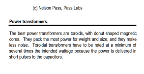
Or straight from the horse's mouth:
Very much do I enjoy this passage from your linked .pdf
Attachments
That’s a fair question and you are not the first and won’t be the last to ask it.Hey all, Got a question. I hope this is not going to start some kind of flame / war, open old wounds etc. This is a question driven out of curiosity and desire to understand!
Given an amplifier of M2X - so 25 watts per channel, 24 volts DC - Why do I need a 400VA / watt supply?
Assuming each channel is going to draw 25 watts - that means I should need 25 x 2 == 50 watts. Watts to volt amps is 1:1, they are the same as I understand it. Did I miss-understand something from the thread? This question should really apply regardless of the amplifier board - this should be mostly universal right?
I was talking with a friend of mine who used to do electronics design at bell labs. When I told him about the power supply he posed the question above to me - I had no answer. I was simply going on what I thought I understood from the thread - that people should buy for 400VA worth of 18VAC.
Thoughts? Are there docs on this - if there are I was not able to find it via google searching or in the forums that I
A class B (and a class AB for that matter) is theoretically 78% efficient. However, in practice they are rarely better than 55 or 60%. You also want to be able to deliver full power at 4 Ohms, so a 25W per channel amp will need (50 * 2)/0.55 =182 Watts. Most designers will allow a further 10-20% safety factor so at a minimum you are looking at a 220W component. About 5% of the total power draw in this type of application will be due to copper and rectifier losses.
For a class A amp, things are a bit different. Unlike a class B or AB amp, the current draw is high and continuous. Class A PP amps are a maximum of 50% efficient but in practice rarely better than 30%. So using the 25W per channel target spec we get (25 * 2)/0.3 =167 W. But, running a 167W component at 167 load is a recipe for trouble in an amplifier and especially a class A amp. Normally, you would play off transformer copper loss temperature rise and core size against the load and try to keep losses in the transformer at or below 10% of the total expected power draw - your transformer supplier will be able to advise you in this. However, most folks are buying off the shelf components, so here you have to have a good hueristic to guide you: take the figure calculated above and double it. This gets the requirement to 330W, so use a 350 to 400 VA component. Note, the 4 Ohm load power is not considered separately as the assumption is the amplifier will exit class A and operate class AB mode at loads < 8 ohms (push pull OPS).
When calculating the required transformer secondary voltage, don’t forget to include the transformer regulation factors - especially in class A amps because the peak capacitor bank load currents are higher than class B/AB amps - an LTspice sim can help here.
So I'm trying to work through the calculations from the linked doc.You can start here:
I don't have a center tap ( secondary ) in my configuration so I'm not sure what to do re where the 38 is coming from. The primary has a center tap but iirc that is unused in this configuration. Also I suspect that at 25watts the current draw would be different? I need to re-read that stuff.Class-A amplifiers operate at the full DC load all the time. This means that for the Figure 2 example, at least 2.5A DC is needed on a continuous basis, requiring a 3A rating for the transformer secondary. Since some extra voltage might be needed to allow for (say) a capacitance multiplier filter, we will give an extra 3V RMS each side. This means that the AC voltage needs to be 38V centre tapped, at a continuous rating of 3A. Using the same formula as above, this gives ...
VA = V × A = 38 × 3 = 114 VA
Anyone have thoughts there?
I am fine with buying a 400VA setup but I want to understand how we get to needing it 😉 This is part of what I'm trying to learn about - why a given thing is needed. I want to have the ideal / appropriate setup 😉Another reason is that 400VA is a medium-sized transformer. A smaller transformer will not cost much less.
Ed
---
If, based on the doc @asuslover pointed out, a 114VA supply is needed at 20V dc then it makes sense that I would need something fairly close to that for 24vdc - guessing something more like 120-130VA range per channel.
If I understand another issue is current draw and voltage droop from the transformer. I experienced this with a 100VA transformer I used on my amp camp amp to switch from switched to linear. When I put a 3d printer heated bed ( iirc 300W at 24vdc ) the voltage went from 24 -> 18 or so. Per the toroid spec when drawing 2.8A the output voltage was spec'd at 18 - which is exactly what I got.
The 200VA coil I was planning to use for this amp is similar - if you draw 5.5A the voltage would be approx 18 there as well. It would be neat if they provided a current/voltage curve - I imagine for ideal usage we would want a fairly flat curve on voltage until nearing the max draw where it hockey-sticks ( eg bends the curve down in voltage at some point ).
Is that part of the idea behind going bigger on the toroid? Keeping enough current available at the target 24v?
The folks at Antec were nice enough to cancel my order while I figure out what I actually need so I thankfully have a bit of time to figure this out now!
Wait until you find out about the heat sink requirements...The folks at Antec were nice enough to cancel my order while I figure out what I actually need
Almost forgot the worst part: the hit on your electric bill!
The heating in the transformer windings is an I^2*R loss. The heating will be greater when the current is drawn in short spikes (as with a diode bridge) than when the current is drawn continuously (as with a resistor).This is part of what I'm trying to learn about - why a given thing is needed.
Ed
Ok so here is what I've come up with so far. Curious for thoughts. I have not taken into account heating - am I in the right ballpark finally?
https://docs.google.com/spreadsheets/d/1muD0yI9WVMbx-2Zw1os8EPKb4-WcR2zK3tsEpWe9OrI/edit?usp=sharing
With 25 watts of the M2x and 18vac/24vdc here is what I come up with:
The spreadsheet is viewable to the world feel free to make a copy/change. There is nothing super special going on. I did make the % efficiency a drop-down so I could choose between different classes. I set class a at 25% based on various findings.
Assuming this is correct each channel of the amplifier needs 120-150VA. I do wonder if this risks getting into voltage drop meaning I would want to over-size the transformer? As at least one other has commented the heating/temperature drop - is that something I need to worry about in this or should I just stay focused on where the spreadsheet / math above shows?
For whatever its worth this does essentially validate the 400VA ( or in my case dual mono, 200VA per channel ) recommendation 😉 Assuming the calculations are done right anyway
Also I did the division against the ac not the dc - is that right? Easy enough to change
https://docs.google.com/spreadsheets/d/1muD0yI9WVMbx-2Zw1os8EPKb4-WcR2zK3tsEpWe9OrI/edit?usp=sharing
With 25 watts of the M2x and 18vac/24vdc here is what I come up with:
| Output power in watts for single channel | 25 |
| Secondary AC voltage | 18 |
| rectifier loss | 0.7 |
| % efficiency | .25 |
| Rectified dc voltage | 24.05584412 |
| input power | 100 |
| current draw on secondary | 5.555555556 |
| VA for secondary | 100 |
| VA with 20% headroom | 120 |
The spreadsheet is viewable to the world feel free to make a copy/change. There is nothing super special going on. I did make the % efficiency a drop-down so I could choose between different classes. I set class a at 25% based on various findings.
Assuming this is correct each channel of the amplifier needs 120-150VA. I do wonder if this risks getting into voltage drop meaning I would want to over-size the transformer? As at least one other has commented the heating/temperature drop - is that something I need to worry about in this or should I just stay focused on where the spreadsheet / math above shows?
For whatever its worth this does essentially validate the 400VA ( or in my case dual mono, 200VA per channel ) recommendation 😉 Assuming the calculations are done right anyway
Also I did the division against the ac not the dc - is that right? Easy enough to change
Last edited:
Just a suggestion, it might be better to start with the required output voltage swing for your power, add to this the output stage voltage drop (4.5V for EF2, 7V for EF3 - these are TOTAL drop across both halves of the OPS using 0.33 Ohm emitter degeneration resistors), add 1.3V for bridge rectifier loss, add 0.2 V for wiring IR loss and then 3-4% for transformer regulation. This will get you your peak secondary voltage. Divide this figure by rt 2 to get RMS secondary voltage.
Is this for class A or AB?
Is this for class A or AB?
So based on the numbers I came up with and this from @Mark Johnson ages ago I feel at least a little more confident. The 300VA would make sense - the numbers my spreadsheet came up with for both channels would be ~240VA and he recommended a 300.For whatever its worth this does essentially validate the 400VA ( or in my case dual mono, 200VA per channel ) recommendation 😉 Assuming the calculations are done right anyway
At least for now Antec does not have the 300 in stock. I'm going dual mono power so 2 x 200va like I was originally doing seems likely the right solution. Based on the numbers it gives me some excess room - not tons like I had worried about.
Hi,
See a quick simulation of a class A 25W amp for illustration.
I choose to leave at least 1A of headroom, so when at maximum power, both transistors will still be draining 1A from each other.
With no signal, output transistors will dissipate around 75W each and the load 0W. Total 150W
At full power, output transistors will dissipate around 60W each and the load 25W. Total 145W.
So, for 2 channels, this little hungry monster really consumes 300W.
I not considering small power dissipated by the drivers and the emitter resistors and the power supply voltage drop.
It's just an illustration.
NO SIGNAL

FULL POWER

See a quick simulation of a class A 25W amp for illustration.
I choose to leave at least 1A of headroom, so when at maximum power, both transistors will still be draining 1A from each other.
With no signal, output transistors will dissipate around 75W each and the load 0W. Total 150W
At full power, output transistors will dissipate around 60W each and the load 25W. Total 145W.
So, for 2 channels, this little hungry monster really consumes 300W.
I not considering small power dissipated by the drivers and the emitter resistors and the power supply voltage drop.
It's just an illustration.
NO SIGNAL
FULL POWER
Schematics are here. https://www.diyaudio.com/community/threads/the-diyaudio-first-watt-m2x.321925
It is class A with +/- 24V rails. The idle current appears to be 1.6A.
I would go with the recommended transformer because the amplifier is consuming maximum power at all times, and the filter capacitors need to be large to reduce hum.
Ed
It is class A with +/- 24V rails. The idle current appears to be 1.6A.
I would go with the recommended transformer because the amplifier is consuming maximum power at all times, and the filter capacitors need to be large to reduce hum.
Ed
If idle current is 1.6A, less current headroom but still kept class A, things get a bit better.
Idle power dissipation is around 80W and full power 90W
2 channels around 180W.
And this calculation means Watt not VA.
Transformer needs to be sized by VA since it is subject to non sine wave current.
VA is higher than Watt due to the power factor imposed by the rectifier diodes+capacitors.
Full wave rectifier has a power factor of around 0.5.
In this case VA should be around 360VA - close to the original specs 400VA.
Last edited:
- Home
- Amplifiers
- Power Supplies
- Power supply sizing question