Tom,
Your calculations are predicated on max voltage drop at the cap.
This is essentially a power consideration, as you naturally want max rail voltage for high amplitude signals.
What if the power angle differs from the subjective issue, in that the max power will not necessarily deliver the best sound at listening levels? This would considerably reduce the metric from 2000uF/amp......
In this I'm reminded of subjective bass response of amps. If you have an amp with a single output pair, bipolar or mosfet, and relatively high Zout, you can actually improve subjective bass response by interposing a small 0.15R resistor into the speaker output line. This promotes overshoot on the voice coil - that is, loss of VC control - but adds a subjectively stronger bass response. Hardly correct in engineering terms, but quite useful when sculpting bass presentation. Perhaps something similar is operating here?
The other aspect you have touched on is decoupling the amp reservoir cap from the power supply filter cap. I use 0.15R between each cap electrode; 0.3R in all. I have found this very greatly improves sonics presumably by greatly reducing speaker earth return currents from intermodulating with charge currents from the rectifier.
Of course, the rail voltage does sag rather more, yet the sound quality is superior. Should this not be the criteria we should address, and if so, why the hell is this happening?
My experience is empirical. I cannot plausibly explain why. But I suspect the issue is much more complex than baseline power calculations suggest.
That said, I applaud what you are doing. Adding some engineering rigour to this vexing issue has been a long time coming....
Cheers,
Hugh
Hugh,
Absolutely. The calculations were done in "worst case" fashion. But under normal listening conditions, not nearly as much would be necessary, especially if low ripple was not a high priority.
Regards,
Tom
I think that depends on the number of bridges.... With one bridge the lowest point of impedance must be at the center tap, that's where the reference is...But one can argue that the return currents must run to the center of the last two caps to make the most of them, this here is difficult as the impedances were talking about in in the micro-milli-Ohm area..
With two bridges this lowest impedance point is between the charging caps and then it could be beneficial to make two gnd-areas separated by a smallish resistor..thus making the dual banks...One bank for charging and one bank for the music...
With two bridges this lowest impedance point is between the charging caps and then it could be beneficial to make two gnd-areas separated by a smallish resistor..thus making the dual banks...One bank for charging and one bank for the music...
Guy's I apologize, for leaving this thread for a week long field trip. Unfortunately I have no laptop and surfing on a cellular phone and typing with ones thumbs I never mastered. I will be following the thread however.
I thrust we come to a conclusion that is both piratical and sonically acceptable. Thank you for all your contributions thus-far.
I thrust we come to a conclusion that is both piratical and sonically acceptable. Thank you for all your contributions thus-far.
Some distortion analysers have a high pass filter at 400 Hz to filter out the fundamental and third harmonic of the mains. Some of the distortion and noise residual could be due to ripple on the power supply.PChi, yes that would be a starting point provided you decide from the outset what ripple you will tolerate, Unfortunately I have not yet devised a test method that can distinguish modulation from the actual signal.
With the equipment I think that it is relatively easy to test checking with and without load and looking at the mains harmonics. This could separate out the inherent mains hum from that coupled from the power supply.
Or use an FFT instead of the distortion analyser.
On a class AB amplifier I think that low distortion can only be achieved if the rejection of the power supply modulation by the audio signal is good.
Hi Nico and all
Just before you go, one last statement from me. You all guys concentrated on caps values as this is the most important issue, wrong. PSU comes together with all the details and if you want to get the most from it, sound wise, than each and every detail has to be correct. Of course we can exaggerate to insane values but that for me is not proper design at all.
Let me just remind you again to the most important steps regarding power amplifier linear PSU design:
- VA rating of mains transformer is calculated from RMS current needed to supply 4 ohm speaker, than multiply this current with AC voltage needed and you will get VA value. Shortly 4 times Wrms results in proper VA rating and this is the first and the most important step at amp PSU design!
- one full wave rectifier on PCB for each rail, so four together for all the rails (two front-end, two output) in one power amp's channel
- on PCB two star grounds (one front-end PSU GND, other output stage PSU GND) connected together with 5-10 mm track, prevents interference between high/low currents in each GND
- 2200 uF/A per single rail is optimum (that 6 words are enough as we speak about caps !!!)
- quality of the electrolytic caps is a must (producer, 105 °C min)
- complete PSU (except mains transformer) located on PCB, resulting in shortest possible connections and the most quality ones - PCB copper 130 um thick
- extra decoupling with 0,1 to 1 uF at tracks splitting and track endings
- direct decoupling between + and - rails with 0,1 uF/250 V
These are practical rules if you want to get the most of sound quality from any amp. 😉
This statement obviously shows that you really don't have an idea how the amps should be designed to get the best sound out of them. Failed on practical implementation, more build, less talk wahab. 😎
Just before you go, one last statement from me. You all guys concentrated on caps values as this is the most important issue, wrong. PSU comes together with all the details and if you want to get the most from it, sound wise, than each and every detail has to be correct. Of course we can exaggerate to insane values but that for me is not proper design at all.
Let me just remind you again to the most important steps regarding power amplifier linear PSU design:
- VA rating of mains transformer is calculated from RMS current needed to supply 4 ohm speaker, than multiply this current with AC voltage needed and you will get VA value. Shortly 4 times Wrms results in proper VA rating and this is the first and the most important step at amp PSU design!
- one full wave rectifier on PCB for each rail, so four together for all the rails (two front-end, two output) in one power amp's channel
- on PCB two star grounds (one front-end PSU GND, other output stage PSU GND) connected together with 5-10 mm track, prevents interference between high/low currents in each GND
- 2200 uF/A per single rail is optimum (that 6 words are enough as we speak about caps !!!)
- quality of the electrolytic caps is a must (producer, 105 °C min)
- complete PSU (except mains transformer) located on PCB, resulting in shortest possible connections and the most quality ones - PCB copper 130 um thick
- extra decoupling with 0,1 to 1 uF at tracks splitting and track endings
- direct decoupling between + and - rails with 0,1 uF/250 V
These are practical rules if you want to get the most of sound quality from any amp. 😉
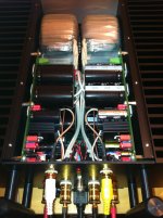
If the power transistors are mounted between the big caps
this is an exemple of how it should not be done...😉
This statement obviously shows that you really don't have an idea how the amps should be designed to get the best sound out of them. Failed on practical implementation, more build, less talk wahab. 😎
Attachments
Last edited:
- VA rating of mains transformer is calculated from RMS current needed to supply 4 ohm speaker, than multiply this current with AC voltage needed and you will get VA value.
Shortly 4 times Wrms results in proper VA rating and this is the first and the most important step at amp PSU design!
The first line contradicts with the second one.
(provided the factor 4 does not refer to a stereo power supply)
The first line contradicts with the second one.
(provided the factor 4 does not refer to a stereo power supply)
... VA per channel 😉
Current capability we need: big, high current, low Zsec transformers !!! 😎
We need caps just for smoothing, setting the ripple to a certain, acceptable level, not to cause 100/120 Hz hum.
The current comes from transformer, not from the caps. Transformer is the most important component of the PSU.
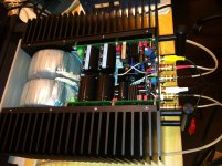
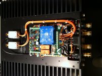
Look to third picture in post #185 and you can see the volume of transformers compared to everything else in a metal case.
Last edited:
The story goes like this:
- SSA/CSA has 62 VDC rail on output and can deliver unclipped amplitude cca. 50 Vp (100 Vpp)/4 ohm
- 50 Vp/4 ohm means 12,5 Ap rail current and converting this to effective current, that is 8,84 Aeff
- 62 VDC comes from secondary power winding of 45 VAC, considering 1,2 V drop on rectifier diodes
- so having 45 VAC muliplied by 8,84 Aeff we get 397,8 VA ie. 400 VA
- each secondary power winding has capability of this current level, because at the same moment only one power winding (among two of them) supplies current. In practice that means we have two 400 VA separate secondary windings on the same 400 VA core transformer
Hopefully I was clear in an explanation of VA rating, from where we get current capability needed to supply our speakers - mains transformer 😉
Last edited:
So 100W/8 dictates a 400VA ?
(love the dual heatsink mounted GBJ type bridge rectifiers )
Yes, 400 VA toroidal transformer per channel, as seen on upper pics. 😉
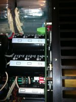
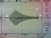
Turning on softly 800 VA and 90000 uF (both dual mono channels together) is served by soft start & utility circuit, located below the amp as showed on pic. Inrush AC mains current showed on graph. 😉
Attachments
Last edited:
The other aspect you have touched on is decoupling the amp reservoir cap from the power supply filter cap. I use 0.15R between each cap electrode; 0.3R in all. I have found this very greatly improves sonics presumably by greatly reducing speaker earth return currents from intermodulating with charge currents from the rectifier. Of course, the rail voltage does sag rather more, yet the sound quality is superior. Should this not be the criteria we should address, and if so, why the hell is this happening?
Beqause the amplifier sees a complex load (the speaker crossover) rather than a pure resistor?
Last edited:
In serious Hi-Fi the calculator only shows the minimum requirement, there will NEVER be a maximum requirement.
If the calcs show a transformer of 100VA, that will do. But there again what car do you need to go get a paper. A mini will do.
My B1 was pefectly happy with a 15VA transformer, it uses only mA, but it does sound better with a 100VA transformer. That takes you down the route of reducing the winding resistance by having a huge transformer.
There must be a limit whan you can't hear the difference. My 100W Class A amps are fine with 600VA power supplies, some guys will use 1000VA supplies.
This is very confusing to say the least, too many differences in opinions.😀
If I wanted to make a 400 watt into 8 ohm/ 650watt into 4 ohm amp, what would the power supply specs be?
Could or would someone make a XL spread sheet or a power supply calculator program that takes into account all of the collective knowledge here? Just within a ballpark, not just one spot on the field.
There was also some talk on another thread about the different TYPES of capacitors too.
Thanks to all for any input.
This is very confusing to say the least, too many differences in opinions.😀
If I wanted to make a 400 watt into 8 ohm/ 650watt into 4 ohm amp, what would the power supply specs be?
Could or would someone make a XL spread sheet or a power supply calculator program that takes into account all of the collective knowledge here? Just within a ballpark, not just one spot on the field.
There was also some talk on another thread about the different TYPES of capacitors too.
Thanks to all for any input.
COST and SIZE have to be vectored into the equation too.
There is not, and will never be a commercial producer who isn't looking after their budget.
Every design is a compromise. Almost every High-End design can be betterred when cost is not an issue.
Every design is a compromise. Almost every High-End design can be betterred when cost is not an issue.

If I wanted to make a 400 watt into 8 ohm/ 650watt into 4 ohm amp, what would the power supply specs be?
Thanks to all for any input.
Optimally would be: 1600 VA transformer per channel, 40000 uF caps per rail. 😉
Optimally would be: 1600 VA transformer per channel, 40000 uF caps per rail. 😉
So two separate chassis and such?
What rail voltage would that be at? plus and minus 80 85 or 90?
And would 100 volt @ 105C power caps be good too or HIGHER
Last edited:
And now were back to bigger is better.....which contradicts my findings...Sorry.
There is feedback in this equation.. that compensates for rail-sag... It seems like there's a delicate balance in things...If I just add capacitance my system losses its speed and sense of space.
There is feedback in this equation.. that compensates for rail-sag... It seems like there's a delicate balance in things...If I just add capacitance my system losses its speed and sense of space.
... VA per channel 😉
Current capability we need: big, high current, low Zsec transformers !!! 😎
We need caps just for smoothing, setting the ripple to a certain, acceptable level, not to cause 100/120 Hz hum.
The current comes from transformer, not from the caps. Transformer is the most important component of the PSU.
Look to third picture in post #185 and you can see the volume of transformers compared to everything else in a metal case.
How could the current come from the transformer and not the caps, if the rectifier diodes are only conducting for a small fraction of each mains cycle?
There is feedback in this equation.. that compensates for rail-sag... It seems like there's a delicate balance in things...If I just add capacitance my system losses its speed and sense of space.
MiiB
I've read this "speed" description before, but have no idea what is meant.
What do you mean by this?
Its especially hard for me to understand "loss of speed" when applied to adding PSU bulk capacitance. If there was a speed affect, however small I would expect an increase in speed.
Thanks
-Antonio
- Status
- Not open for further replies.
- Home
- Amplifiers
- Power Supplies
- Power Supply Resevoir Size