This is the followup from:
Schematic hunt: RIAA Phono Preamp
It took me a little over a year to round up all the parts, but mostly just to find some personal bandwidth to dig into this in earnest. I just finished prototyping the tube rectified LCLC power supply found at the bottom here:
RJM Audio - Tube passive phono preamplifier
I followed every component spec to the letter with the only exception being the transformer is 620VCT vs. the specified 625VCT, but the 0.8% variance is almost certainly less than the manufacturing tolerance.
Hammond 372X datasheet:
http://www.hammondmfg.com/pdf/EDB372X.pdf
I fired it up, and checked the output immediately (didn't wait for it to warm up in case I screwed something up). I should see 250-300V from B+ to ground, but I'm actually getting 475VDC!!! Something is very very wrong. Blow up components wrong! Or I'm just an idiot wrong... Very much a possibility here. First rodeo of this sort.
My Fluke is only good for 600V AC/DC, so I can't test for the 620V output of the transformer secondary coil, but I can test from each of the 310V sides of the 620VCT output coil to 0V, and they're giving me 348V. That's ~11% high, and probably within manufacturing tolerance*. My mains current is 123V as of just now (I used the 120V blu/brn and wht/blk leads for the primary coils).
What could I have messed up and how to get such a high output voltage from this power supply?
*Looking closer at the transformer datasheet, I see that the wiring setup for what's supposed to be 620VCT is actually expected to output 340.0V +/-2% with 120V, which is very close to the 348V I got, but not at all the 310V printed elsewhere on the same datasheet/half the 620V that's on the sticker on the physical component...?
Last edited:
That is a tube rectified, choke filtered supply. The unloaded voltage will be much higher - your readings make sense. The cap will charge to the peak voltage, not the average. As soon as you put enough load on it, the voltage will drop into range. The additional 11% high is the regulation figure of the transformer itself.
Because the no-load start up voltage is so high, you need to use 500 volt caps. Even coupling caps insure the circuit need to take this into consideration.
Because the no-load start up voltage is so high, you need to use 500 volt caps. Even coupling caps insure the circuit need to take this into consideration.
Put a small load on it
Transformer secondary voltages are often specified at full load current. Put a light load on the transformer and see if the secondary voltage drops to within spec.
Transformer secondary voltages are often specified at full load current. Put a light load on the transformer and see if the secondary voltage drops to within spec.
It's not clear to me which schematic you used for the preamp but the power supply you use has a choke input filter. A filter like that has to pass more than a certain amount of current and/or the inductance of the first choke has to be high enough to do its work properly. If the value of the inductance and/or the amount of current is too low, the output voltage of the filter will be much higher than it should be. See the formula for "minimum choke inductance" in this link: https://www.dhtrob.com/overige/pdf/ps_07.pdf
He said the tube rectified LCLC version. The inductor is ALWAYS too small for proper regulation at start up before the amplifier tubes start drawing current.
In case your comment was adressed to me: Didn't I write about the LCLC version than? What I don't know is the schematic of the preamp, and because of that I don't know how much current it uses.
The power supply has the indirect heated 6CA4 as rectifier so (atleast to me) it's unknown if the rest of the tubes start to draw current later than the 6CA4.
The power supply has the indirect heated 6CA4 as rectifier so (atleast to me) it's unknown if the rest of the tubes start to draw current later than the 6CA4.
About 4 mA per tube, times four - about 16 mA. 20H choke input filter needs about 66 mA to regulate, so you'd need to add a bleeder resistor to get the supply to regulate... but the current would exceed the choke's 30 mA rating. A higher value choke would need less current, waste less power in bleeder.
I was under the impression that the OP was attempting to test the power supply, before subjecting the preamp to it. The behavior he is getting is consistent with running it unloaded.
If the preamp tubes draw 5 mA each, X2 channels, the supply should be tested with a 15k resistor as a load. It would normally dissipate 6 watts. Oversize to 10 or 20 for test purposes, just in case something goes over voltage. Use several of whatever you happen to have in series/parallel to get near the right value and enough watts. Even six 100k in parallel or 15 1k’s in series would do it (don’t worry about buying a special resistor, use what you have).
If the preamp tubes draw 5 mA each, X2 channels, the supply should be tested with a 15k resistor as a load. It would normally dissipate 6 watts. Oversize to 10 or 20 for test purposes, just in case something goes over voltage. Use several of whatever you happen to have in series/parallel to get near the right value and enough watts. Even six 100k in parallel or 15 1k’s in series would do it (don’t worry about buying a special resistor, use what you have).
Oops - key bounce in my calculator gave the wrong number - it's more like 16 mA minimum, which might not need a bleeder to regulate - still required for safety, but needn't dissipate as much power.
OK... Lots happened overnight. Love it! Great information, and I didn't screw up to boot! The "I don't know what I'm doing" explanation is awesome, because the whole point of this project is to get my feet wet and learn. I found and followed all the safety protocol, and that's the important part.
I can't figure out how to get the multiquote feature to work on this forum, so I'll do it manually. Hopefully the lack of notification isn't too much of an issue.
*Explain it like the person you're explaining it to nearly had a heart attack from the high voltage, and not in the usual way. This is my first attempt at such a project.
A test load makes perfect sense. I have a 20K 5W a 2K 5W resistor that I have set up for bleeding off the capacitors on shutdown. I have random other resistors lying around. 15K is easily doable, I just need to figure out the 6W. I don't have any other high wattage resistors that aren't already spoken for/in use. How much headroom is in that 6W figure?
The preamp being powered is the schematic at the top of the same page. I'm not being very creative here at all. This project is intended to be just a slight bit more involved than your typical LEGO set. The challenge is in learning the ropes of the genre.
By luck, the choke I sourced is a Hammond 193C (datasheet: http://www.hammondmfg.com/pdf/5c0033.pdf), and it's rated for 100mA. The second choke is a Hammond 156L (datasheet: http://www.hammondmfg.com/pdf/5c0032.pdf), and it's rated for 75mA. Hopefully, that bullet is sufficiently dodged.
I think I just need to figure out a way to load it sufficiently, and then retest. I didn't think this was a very complicated schematic, and my friend who is far more electronically inclined (albeit certainly not full analog high voltage circuitry) called it one of those projects "for when you really just need a win", which I took to mean pretty much fool proof. It looks like this fool managed to not break anything, but this idiot didn't even realize he hadn't! I call it a win!
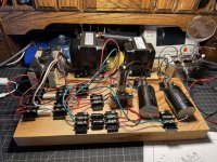
Photo attached of my "breadboard" for prototyping. Very temporary, just to make sure my cluebox is at least half full. I intend to make a similar mock up of one channel of the preamp, test off the turntable to make sure noises come out that sound vaguely familiar, then I need to figure out a proper enclosure situation and execute for real!
I can't figure out how to get the multiquote feature to work on this forum, so I'll do it manually. Hopefully the lack of notification isn't too much of an issue.
My understanding is that RJM is a well known and respected individual around these parts, this schematic has been around for 20 years, and has been successfully built hundreds, if not thousands, of times successfully. This, combined with the design parameters discussed in the thread linked above, are why I chose this schematic to build. I'm not doubting what you say, especially not given what I saw when I fired it up last night, but there is a bit of a burden of proof here. Please explain.*wg_ski said:Because the no-load start up voltage is so high, you need to use 500 volt caps.
*Explain it like the person you're explaining it to nearly had a heart attack from the high voltage, and not in the usual way. This is my first attempt at such a project.
ALKVA said:Transformer secondary voltages are often specified at full load current. Put a light load on the transformer and see if the secondary voltage drops to within spec.
wg_ski said:I was under the impression that the OP was attempting to test the power supply, before subjecting the preamp to it. The behavior he is getting is consistent with running it unloaded.
If the preamp tubes draw 5 mA each, X2 channels, the supply should be tested with a 15k resistor as a load. It would normally dissipate 6 watts. Oversize to 10 or 20 for test purposes, just in case something goes over voltage. Use several of whatever you happen to have in series/parallel to get near the right value and enough watts. Even six 100k in parallel or 15 1k’s in series would do it (don’t worry about buying a special resistor, use what you have).
A test load makes perfect sense. I have a 20K 5W a 2K 5W resistor that I have set up for bleeding off the capacitors on shutdown. I have random other resistors lying around. 15K is easily doable, I just need to figure out the 6W. I don't have any other high wattage resistors that aren't already spoken for/in use. How much headroom is in that 6W figure?
PFL200 said:It's not clear to me which schematic you used for the preamp...
PFL200 said:What I don't know is the schematic of the preamp, and because of that I don't know how much current it uses.
The power supply has the indirect heated 6CA4 as rectifier so (atleast to me) it's unknown if the rest of the tubes start to draw current later than the 6CA4.
The preamp being powered is the schematic at the top of the same page. I'm not being very creative here at all. This project is intended to be just a slight bit more involved than your typical LEGO set. The challenge is in learning the ropes of the genre.
Tom Bavis said:About 4 mA per tube, times four - about 16 mA. 20H choke input filter needs about 66 mA to regulate, so you'd need to add a bleeder resistor to get the supply to regulate... but the current would exceed the choke's 30 mA rating. A higher value choke would need less current, waste less power in bleeder.
By luck, the choke I sourced is a Hammond 193C (datasheet: http://www.hammondmfg.com/pdf/5c0033.pdf), and it's rated for 100mA. The second choke is a Hammond 156L (datasheet: http://www.hammondmfg.com/pdf/5c0032.pdf), and it's rated for 75mA. Hopefully, that bullet is sufficiently dodged.
I think I just need to figure out a way to load it sufficiently, and then retest. I didn't think this was a very complicated schematic, and my friend who is far more electronically inclined (albeit certainly not full analog high voltage circuitry) called it one of those projects "for when you really just need a win", which I took to mean pretty much fool proof. It looks like this fool managed to not break anything, but this idiot didn't even realize he hadn't! I call it a win!
Photo attached of my "breadboard" for prototyping. Very temporary, just to make sure my cluebox is at least half full. I intend to make a similar mock up of one channel of the preamp, test off the turntable to make sure noises come out that sound vaguely familiar, then I need to figure out a proper enclosure situation and execute for real!
Attachments
Last edited:
An LCLC based power supply is a little overkill for a couple of preamps consuming total of 20mA at 250V. For my preamp and small tube mixer designs I use a simple low cost CRCRCRC. With a semiconductor bridge rectifier you only need a mains transformer with a 240V secondary rated at about 35mA. This will give an unloaded output of around 340V. To drop this to 250V with a 20mA load requires (340-250)/20 = 4.5K of series resistance which can be made of 3 x 1K5 resistors. With 220uF capacitors ripple will be reduced by more than 200 times per stage. Initial ripple on the first cap will be about 1V peak to peak which the three stage filer will reduce to less than a microvolt.
Cheers
Ian
Cheers
Ian
The schematic was selected more than a year ago. I'm essentially just following a recipe at this point, and using it as a learning exercise/entree into high voltage analog circuitry.
If @wg_ski or @ALKVA (apparently you can't tag people on this forum...) specifically, but anyone who knows more than I do would like to weigh in on the necessity of the 500v rating on the LCLC capacitors and/or what would be a minimal functional load to properly test the power supply (or even better would be whatever calculation required to figure it out), it would be appreciated.
If @wg_ski or @ALKVA (apparently you can't tag people on this forum...) specifically, but anyone who knows more than I do would like to weigh in on the necessity of the 500v rating on the LCLC capacitors and/or what would be a minimal functional load to properly test the power supply (or even better would be whatever calculation required to figure it out), it would be appreciated.
500V caps should be used because the unloaded voltage can get to 475 volts. If they are just good for the rated operation voltage when the choke is regulating, you could run into problems if a tube isn’t working (or unplugged).
I think Tom calculated 16mA for the 20H choke to flywheel properly - 15 mA from a 20k load is probably close enough. May run a few tens of volts high, but not the end of the world. Those chokes will have a bit more inductance at less than rated current anyway. 100 mA choke is overkill (and expensive). But since you already have it…..
I probably would have done several sections of RC filter starting with a 250V (or 250-0-250) trafo and cap input filter so that 400V caps are good enough, but I’m a cheapskate and not allergic to silicon rectifiers, either. The choke input supplies *do* let you use smaller uf caps, which is good if you are also allergic to electrolytics. 600 volt 20 uF polypropylenes are certainly possible and not *totally* outrageous.
I will probably go and upgrade those capacitors so that I don't end up with one failure cascading into multiple others.
The 100mA choke may be overkill, but it was the smallest and onliest 20H choke good for at least 30mA at either DigiKey or Mouser, so that's what I ended up with. As previously stated, this is my first foray into this part of the hobby, so I don't have much in the way of expectations for what constitutes things being expensive or not. $53.XX is the cheapest 20H >30mA choke I've ever seen. Also the most expensive (actually, I think DigiKey might have had the potted version as well, which would have been much more expensive). I'm not trying to build the end-all be-all phono preamp here. I'm looking for a 99% solution. All tube from stem to stern, minimal part count, point to point. Simplicity. Primary purpose is to learn.
The 100mA choke may be overkill, but it was the smallest and onliest 20H choke good for at least 30mA at either DigiKey or Mouser, so that's what I ended up with. As previously stated, this is my first foray into this part of the hobby, so I don't have much in the way of expectations for what constitutes things being expensive or not. $53.XX is the cheapest 20H >30mA choke I've ever seen. Also the most expensive (actually, I think DigiKey might have had the potted version as well, which would have been much more expensive). I'm not trying to build the end-all be-all phono preamp here. I'm looking for a 99% solution. All tube from stem to stern, minimal part count, point to point. Simplicity. Primary purpose is to learn.
Just for closure, I just tested it out with the 20K 5W resistor, and it's putting out 300V on the nose! Moving on to one half of the phono stage!
Back in the days of choke input filtering there was typically always a large ww resistor load - par for the course - but many are obviously not aware.
One option nowadays are also active load solutions, where a load is engaged when voltage exceeds a certain level.
The robust option is to use caps with acceptable voltage rating, but that may get complicated for all supply and coupling caps in an amp.
One option nowadays are also active load solutions, where a load is engaged when voltage exceeds a certain level.
The robust option is to use caps with acceptable voltage rating, but that may get complicated for all supply and coupling caps in an amp.
- Home
- Amplifiers
- Tubes / Valves
- Power supply question