Would it be an issue to run a voltage doubler on a 170v power transformer secondary alongside a traditional bridge rectifier? I would like to be able to use something like a 12ax7 on the front end of an amplifier driving a 6gc5 for output. The preferred plate voltages are wildly different though. Using power resistors to drop 140v @ 90 mA for the 6GC5s (if I were to just get a 340v transformer) would be very wasteful. Since the 12ax7's would only need 1.2 mA per triode, it would seem that a doubler wouldn't have much issue supplying the current. Having it connected to the same secondary as the vanilla power supply though... Would that be an issue? I'm hoping that I can make use of this 170v transformer along with those 6GC5s but am just having trouble getting any triode to draw enough current with such low B+. I got a pair of 6dj8s but the best that I've been able to achieve is ~3 mA at 60v or so. Not exactly an ideal place to be. If it's just going to be unadvisable to use the doubler in that way ten I'm likely going to break down and change the topology of what I'm working on.
Last edited:
Jason,
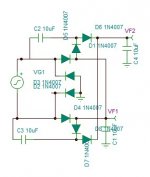
If you have yet to source a power transformer, get something with a 170-0-170 rectifier winding. 2 full wave rectified rails, 1 "tall" and 1 "short", require only 5 diodes. The "tall" rail is bridge rectified and the "short" rail is FWCT. The provided example shows vacuum rectifiers combined with Schottkys, but 100% SS works well too.
If you have yet to source a power transformer, get something with a 170-0-170 rectifier winding. 2 full wave rectified rails, 1 "tall" and 1 "short", require only 5 diodes. The "tall" rail is bridge rectified and the "short" rail is FWCT. The provided example shows vacuum rectifiers combined with Schottkys, but 100% SS works well too.
Attachments

Awesome sauce! Thank you. Polarity on c2 and c3 should both have negative on the left, correct?
Correct.
Attached is a useful link on the power supply kokoriantz shows. It's where I found the circuit a few years ago when I had a similar application.
the best voltage doubler -the 4X8!
the best voltage doubler -the 4X8!
...draw enough current with such low B+.....
How much current do you figure you need?
The 6GC5 is similar to 25L6. Which was designed to run at 110V-200V with a general purpose triode driver working on the same (actually dropped) supply. Grid drive is under 10V, grid resistor 100k, so 0.1mA of drive current. A 1mA driver is not real strained. Input capacitance is like 30pFd so drive current does not rise until 50kHz. And with only 8V drive needed a 12AU7 would take-up most line inputs. For more gain and NFB a 12AT7 is a fine tube.
Awesome. Thanks for the input. That multiplier looks a little nuts but I'm going to build one. I bought the transformer a while back, assuming that I could do something with it. (Edcor XPWR094) I had originally intended to run this with those 6DJ8's but I had trouble developing enough current at a reasonable voltage. I'd have to lower the plate resistor to 10k just to get 7 mA at about 90v. I'm assuming that this cut my voltage gain down to nearly nothing, because I could only barely hear anything with it like that. Larger plate resistors would drop plate voltage and current to what seems to be non-linear territory. I was seeing about 40v at 1 mA from what I can remember with a 47k plate resistor. I found the Hammond 270FX (250-0-250, 5v, 6.3v) over on mouser but that bad boy is $90. Then I asked about doublers instead. The Edcor that I have now is rated to 250 mA on the 170v secondary. Unless my math is off, it should be able to supply the current required with a decent safety margin. I'm not particular about which triode I use, so long as I can keep it linear and so long as it'll make the 6gc5 happy. The 12ax7 is just what I think of when I think "triode." I'm extremely happy with the sound of the 6gc5 though, so I'd really like to keep them on board if at all possible. There's also the novelty of it being a fat 9-pin noval tube. Oh, and they're dirt cheap.
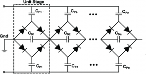
FWIW, the most sophisticated voltage multiplier I am aware of is the provided full wave series/parallel setup. Each stage is a 4 diode bridge. Polarized electrolytic caps. are OK in the series positions, but (IMO) caution requires AC rated film caps. in the parallel positions. The required voltage rating of the parallel position caps. increases, as "movement" away from the point of AC application occurs.
Bipolar PSUs, with possibly differing rail voltages, are possible using this technique. On the AC feed "side", all that's needed is a simple winding of sufficient V/A rating.
Bipolar PSUs, with possibly differing rail voltages, are possible using this technique. On the AC feed "side", all that's needed is a simple winding of sufficient V/A rating.
Attachments
The more simple you make it, the more complex it becomes.
Depending on the voltages and currents, multi tap or multi winding transformers make things easy.
So do a pair of transformers.
Easy for some is cheaper than complexity stealing your time.
How many diodes, how many capacitors, electrolytics, non electrolytics, etc.?
Lay the complex circuit out, do not make any mistakes (not on a power supply, it is too hard to put the smoke back in).
"You should make things as simple as possible, but no simpler" - Albert Einstein
Last edited:
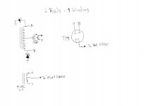
How about this . . .
A single center tapped high voltage secondary.
Ground the center tap.
Then . . .
A. 2 diodes, and a cap input filter. 1/2 winding Vrms x 1.414 = DCV out.
and . . .
B. 2 diodes, and a choke input filter. 1/2 winding Vrms x 0.9V = DCV out.
(do not forget to calculate the resistive DC drops)
Ratio of the two B+ voltages (disregarding resistive drops), is 1.57:1.
Will that work for you?
Yes, I realize you have to use one choke, and two separate filter networks.
For me, I just do the calculations for B+ voltage, and ripple by long hand.
(I hate power supply software, and other kinds of software too).
Last edited:
For output tubes like this, and 50C5, 6W6, etc. it’s nice to just be able to use an isolation transformer to make 170 volts for the B+ instead of paying premium for a tube application transformer. And 170 will work for the front end. But you can also just use a 120 to 120/240 isolation trafo to make a 170-0-170 supply. Then just ground the negative leg and have 170 and 340 available. This also works where you want it the other way around, with a B+ at 340, and a separate 170v for a screen supply, for instance. 6W6s will run quite well this way in AB p-p, and the 6CG5 probably will too (at a higher load impedance and higher power). They may even be the same guts inside with different ratings.
Grounding one end of a 0-170-340 secondary makes it easy to create 2 B+ voltages.
The problem is, connected that way, you can only have 1/2 wave rectification.
If you like 1/2 wave rectification, great!
Just remember the maximum current rating for a transformer secondary is significantly reduced for 1/2 wave rectification that drives a capacitor input filter.
You can not put one bridge rectifiers across the 170V and one bridge rectifier across 340V; and you can not put a Voltage doublers across the 170V, and a voltage doubler across the 340V windings, and have the two B+ supplies share a common ground.
And you can not mix one to have a voltage doubler, and the other to have a bridge rectifier, and then have the two B+ supplies share a common ground.
Did I miss something?
All the solutions have some kind of tradeoff. Just determine what is most important, and settle on a design.
Last edited:
You can do full wave like that - you’re not limited to half wave. You’re thinking of a doubler where you connect to the middle. You need to start with a 120-0-120 trafo which would still be a commodity item. Just connect it as you would a big solid state amp supply, but ground the bottom not the center. The 340 volt is a full wave bridge, and the 170 a 2-diode full wave center tapped with the diodes in the ground side. You may be stuck with cap input filters - I’ve never tried it with chokes. I do this for big class H amps all the time - one transformer for high and low + rails, one for the -‘s. I’ve got a tube amp in the works now using this - the 200 volt mid rail is for the screen supply (6LR8 vertical sweep tubes).
Pete Millett publicized 2 full wave rectified rails from 1 CT winding, some time ago. I'm providing an illustrative example that employs both SS and vacuum rectifiers, but 100% SS diodes works too. The "tall" rail is bridge rectified and the "short" rail is FWCT.
The example has a low current "tall" rail and a high current "short" rail, but all sorts of variations, including 1 rail choke I/P filtered and the other cap. I/P filtered, are feasible.
The example has a low current "tall" rail and a high current "short" rail, but all sorts of variations, including 1 rail choke I/P filtered and the other cap. I/P filtered, are feasible.
Attachments
Do you know where that's from Eli? I just can't see any advantage over the bridge scheme wg_ski referred to.
EDIT: without knowing more, the only reason I can see for the 5U4 is that the 1/2V rail doesn't come up faster than the V rail.
EDIT: without knowing more, the only reason I can see for the 5U4 is that the 1/2V rail doesn't come up faster than the V rail.
Last edited:
Do you know where that's from Eli? I just can't see any advantage over the bridge scheme wg_ski referred to.
EDIT: without knowing more, the only reason I can see for the 5U4 is that the 1/2V rail doesn't come up faster than the V rail.
I made those "hen scratches". I was illustrating the technique for vacuum rectification aficionados. What's needed is a set of 5 diodes. The SS diodes (low forward drop) between the ends of the rectifier winding and ground are involved in both rails and need to have an appropriate current handling capability.
Theoretically, a diode is not needed on the CT. Practically is another matter. Things can go wrong and the 5th diode provides a margin of error. Also, when PN diodes are used for the ground connections, a vacuum or Schottky 5th diode blocks PN diode switching noise from reaching the "short" rail filter.
The method uniformly distributes the net stresses across the center tapped rectifier winding.
The net rails need not have a roughly 1:2 ratio. For instance, choke I/P filtering the "tall" rail and cap. I/P filtering the "short" rail will make the net ratio quite a bit smaller than 1:2.
BTW, since the 5U4 is directly heated and the 7Y4 has a cathode sleeve, the "short" rail will still "rise" 1st. I was simply showing a low current "tall"/high current "short" configuration.
Last edited:
wg_ski,
Did I misunderstand your Post # 15?
Was this what you essentially proposed?
Ground one end of a 120-0-120 secondary.
Connect a bridge across the complete secondary (to 120 phase 1, and to 120 phase 2).
Now, connect the minus (-) output of the bridge to ground (you need a ground reference for the B+), Right?
Seems like . . .
Short! Smoke!
- Home
- Amplifiers
- Tubes / Valves
- Power supply question - Voltage Doublers