I also had a look at the e-choke circuit. With the time switch OFF it performs way below for const. avg. loads as in class A amps. Maybe there are advantages for changing loads, but I am not interested.
If you use time switch ON, the e-choke is more or less the same circuit as in post #1, a few more parts smooth out the remaining ripple (make it more sine like), but the response under load is much more flaccid. Talk about choosing your poison.
If you use time switch ON, the e-choke is more or less the same circuit as in post #1, a few more parts smooth out the remaining ripple (make it more sine like), but the response under load is much more flaccid. Talk about choosing your poison.
Hi - stumbled across this post and your circuit. Looks interesting and worth a shot to reduce hum on a single-ended EL84 my son has built from kit. I see the post is from 2014, and you're still active 🙂 so, any suggested mods or improvements for the circuit? I know that C in has to be calulated according to actual current drawn so as not to upset tube rectifiers. Thanks in advance!Search for Mosfet Gyrator - the schematic posted above (as DF96 says) is NOT a simulated inductor supply, it is a simple capacitance multiplier.
The "real" gyrator supply emulates the chokes "resistance to current change" behaviour and is reputed to sound much better than a capacitance multiplier "ripple filter".
Here is one which can operate as a true simulated inductor (link out) or in a mode with reduced simulated inductor behaviour but capacitance multiplier function added (link in) - search "E-Choke" and you will find where you can buy this "off the shelf".
Cheers,
Ian
By the way... what's the function of the (non Zener) diode? Would that be a standard 1N4007 or similar? Thanks.Hi - stumbled across this post and your circuit. Looks interesting and worth a shot to reduce hum on a single-ended EL84 my son has built from kit. I see the post is from 2014, and you're still active 🙂 so, any suggested mods or improvements for the circuit? I know that C in has to be calulated according to actual current drawn so as not to upset tube rectifiers. Thanks in advance!
for me it's just a matter of taste. How many people think that a tube amplifier is just euphonic and build it just like that.Dear members,
Please take a look at the attached very simple power supply ripple filter.
Key performance figures:
406 V offload voltage
134 mA quiescent current
14 mVpp ripple
These are comparable to a 15H choke (~100R Rdc), yet you can get all parts for the mosfet filter for less than 1€, compared to the price of a decent choke.
Am I missing something, or why are chokes still so popular in our tube amp power supplies?
Cheers
I read a while ago that in a blind test an old push-pull Radford amp was considered the best sounding.
Late to the party, but interested in this circuit. I see several resistors in the schematic '1m'; I presume these are meant to be 1M, not 1milli?Search for Mosfet Gyrator - the schematic posted above (as DF96 says) is NOT a simulated inductor supply, it is a simple capacitance multiplier.
The "real" gyrator supply emulates the chokes "resistance to current change" behaviour and is reputed to sound much better than a capacitance multiplier "ripple filter".
Here is one which can operate as a true simulated inductor (link out) or in a mode with reduced simulated inductor behaviour but capacitance multiplier function added (link in) - search "E-Choke" and you will find where you can buy this "off the shelf".
Cheers,
Ian
Jan
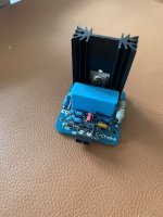
Coincidentally I have the board(s) in front of me and there are 3 x 1 MOhm. Maybe milliOhms are a little unlikely as literally everything in tube audio is high ohmic. Unfortunately the trend in the anglosphere is to write units deliberately erroneous like Db, hZ, Va, vA, mhZ, Ma, ma, v, Uf, uf, mmf, Kohm etc.
Forgot where the boards came from but make sure your version has connector blocks capable of the DC voltages and standoffs to have enough clearance to the DC voltages. This one needs plastic standoffs. The designer included a 0.5A fuse which is good thinking.
Forgot where the boards came from but make sure your version has connector blocks capable of the DC voltages and standoffs to have enough clearance to the DC voltages. This one needs plastic standoffs. The designer included a 0.5A fuse which is good thinking.
Attachments
Last edited: