Have you looked at the inductor values in a mains interference filter?
.5mH to 10mH is common.
Do you call that huge?
Or insignificant @ 50/60Hz?
.5mH to 10mH is common.
Do you call that huge?
Or insignificant @ 50/60Hz?
Have you looked at the inductor values in a mains interference filter?
.5mH to 10mH is common.
Do you call that huge?
Or insignificant @ 50/60Hz?
Truly insignificant! Just wondering up to where it could be raised - 100mH should be ok?
I was planning to use some 10mH inductors to filter the mains. 🙂
I would be careful when using higher inductance. If low resistance is a requirement then higher inductance will introduce impedance peak, making it worse in some lower frequencies. I would always put some resistance in series with inductance to lower the Q. Always check with LTSpice and find the minimum resistance value for a given inductance.🙂
I would be careful when using higher inductance. If low resistance is a requirement then higher inductance will introduce impedance peak, making it worse in some lower frequencies. I would always put some resistance in series with inductance to lower the Q. Always check with LTSpice and find the minimum resistance value for a given inductance.🙂
Well yes, I don't think I would put anything bigger, just to know.
You mean to perform AC analysis on the filter section and check no peaks are introduced? Which means a generally flat transfer function up to a point and then it gradually falls. If it is this what you mean, yes I always do it!
edit: nigelwright7557, in the schematic you posted, these are two separate inductors or a common mode choke?
So, I understand that mains filters suppress not only incoming noise, but also noise that the filtered equipment could produce and distribute across mains wiring.
Then, what would be the benefits of a mains filter for a regulated linear supply? To explain myself:
(1) Do linear supplies produce considerable noise that travels backwards into mains? If such noise would come only from rectifier action, then would a snubber ensure that most of this HF garbage is contained in the snubber loop and does not reach mains - removing the need for a mains filter, in that manner?
(2) Would the regulator presence ensure that nobody cares about HF garbage that enters the appliance? Linear regulators usually don't have as good HF PSRR as they do for LF, so is actually a regulator a benefit against mains noise, instead of a passive power supply design?
Of course, a filter can't harm either (especially in a regulated design - I note this, since I know people could chime in saying "a filter decreases dynamics"), so I just want to know whether it is better to avoid it if possible, in order to save space, work and costs. 🙄
I believe your first assumption is correct. Snubbing reduces the spread of harmonics in both directions. Exported to the Mains' wiring and imported into the Receiver's circuits.
A regulator usually reduces imported noise. But I don't think that means anything about what effect it has on exported noise.
A Mains' input filter, filters in both directions, both the imported and the exported. When designed correctly, it should not interfere with the passage of the wanted audio signal.
Yes, but as you have also stated before based on Ott, if you build it on your own, you have to shield it too - which means that you have to use another aluminum box inside your chassis, and spend time attaching it to the chassis.
Or you can buy an existing, off-the-self product. I will see what I can get downtown. 🙄
How about these two?
10VK1 TE Connectivity / Corcom | Mouser
FN2030B-8-06 Schaffner | Mouser
My application is a 100VA transformer, and maximum rms current should not exceed around 350mA, so peak primary should not be above 1.05A too.
A couple of questions:
(1) Are these off-the-self filters protected against voltage surges? I don't mean including a MOV that will protect the equipment, I want to know whether they are in danger when not having one (thus reliability is reduced).
(2) Say I use a pcb Schaffner filter. And all this is put into a metal box, inside the equipment's own metal box. And I use a Neutrik powercon (or other IEC plug) to feed mains into the equipment. So, cables will run from the inlet to the box containing the EMI filter. Would this render the filter useless to some degree, since before mains gets filtered, it is able to radiate HF noise inside the equipment?
The X and Y rated capacitors are tested to be safe with interference spikes exceeding around 2500Vpk. I seem to recall seeing around 8000Vpk for a Y1.
Some interference of very short duration may exceed the test voltages for the X & Y rated capacitor. They are designed for that eventuality. They are self healing.
repeated exposure to excessive interference gradually uses up the capacitance value, i.e. their useful life is not infinite.
Here's a couple of links to pdf:
http://www.google.co.uk/url?sa=t&rc...=2hoIB3G_EYGVymHVPresvA&bvm=bv.59930103,d.ZG4
http://www.google.co.uk/url?sa=t&rc...=oGqbk3Cs-rdXCc-Z04rm2g&bvm=bv.59930103,d.ZG4
The case around the filter should enclose the cable feeding from chassis to case, for good interference suppression.
You are right, exposed cable reduces the effectiveness of the filter.
Last edited:
Try an x2 cap right across the line and neutral on your IEC socket. Works for me been doing that for years now. This will filter most if not all the crap from the line and get it before entering you case/chassis.
Cheers,
Bob
Cheers,
Bob
I prefer filters like the Schaffner FN9222 that are incorporated into the IEC socket itself. The filter is encased in its own small metal box which contacts the chassis (it's bolted to the chassis), AND the metal box has an explicit FastOn / solder lug so you can attach a thick copper wire for Protective Earth.
You get the shortest possible wire length (between mains and EMI filter) and the best possible Faraday shielding around the filter itself. What's not to like?
You get the shortest possible wire length (between mains and EMI filter) and the best possible Faraday shielding around the filter itself. What's not to like?
Attachments
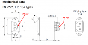
I prefer filters like the Schaffner FN9222 that are incorporated into the IEC socket itself. The filter is encased in its own small metal box which contacts the chassis (it's bolted to the chassis), AND the metal box has an explicit FastOn / solder lug so you can attach a thick copper wire for Protective Earth.
You get the shortest possible wire length (between mains and EMI filter) and the best possible Faraday shielding around the filter itself. What's not to like?
Price probably - x2 cap maybe 50 cents + IEC socket $3.50
Shortest distance with X2 cap soldered right onto the line and neutral doesnt get any shorter than that, probably exactly whats inside those fancy IEC sockets anyways.
Cheers,
Bob
That is exactly what I was going to post - what I seem to like the most (and don't think that is easily achievable) is the fact that shielding is almost perfect.
The solution I had in mind was to panel-mount everything (Neutrik powercon, fuse, switch + pcb with a filter and soft-start) on the vertical back wall of my equipment, and then buy an off-the-self Hammond diecast aluminum box, which I would use to cover all the aforementioned circuitry. 4 holes in the back wall, and you are done with fixing it - it already has the screw threads to tighten it against the wall. Lid goes unused.
Then, you would only have to drill another hole to exit the final L/N combination towards the transformer primary, which should be manually extended to the end of the box so that the box could be used as a removable cover for the mains circuit + the wires going to the transformer primary. Careful insulation up there, using rubbers + extra wire insulation (probably multiple heatshrink tubing), and you are done.
So when you open the equipment, all you see is you transformer and everything that follows it, the transformer being "magically" powered from a diecast box. No mains seen to interfere with, safe as it gets.
But, would the box be tightened rigidly enough to the outer chassis to ensure proper shielding? Tim Williams reminds us that the maximum dimension of an aperture determines the attenuation of the external fields, so if the box fails to be make an even, strong contact with the outer case, it could spoil the entire shielding process, providing a path for HF garbage to enter the equipment before any filter kills it.
This is why I will maybe lean towards Mark's solution. Or would you think that the method I described above could be worth anything? 🙄
Last edited:
Done that, but you really need a wire mesh gasket between the box and the rear panel (Or some berillium copper 'finger strip' to make sure you have good contact and that the gaps are smaller then the highest frequency of interest.
Wurth (Among others) make parts that fit the bill for this kind of thing.
TBH the only time I would bother is if either dealing with a known very high RF field (Think on an AM broadcast site) or when doing something small signal at insane impedances like NMR imaging or running a He3 detector.
Regards, Dan.
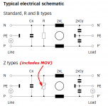
The FN9222Z {see attached image} contains... X2 cap ... probably exactly whats inside those fancy IEC sockets anyways.
- an X capacitor ("Cx")
- a Metal Oxide Varistor ("MOV")
- a common-mode choke ("2xL")
- two Y capacitors ("2xCy")
- a metal casing
Attachments

Done that, but you really need a wire mesh gasket between the box and the rear panel (Or some berillium copper 'finger strip' to make sure you have good contact and that the gaps are smaller then the highest frequency of interest.
Wurth (Among others) make parts that fit the bill for this kind of thing.
TBH the only time I would bother is if either dealing with a known very high RF field (Think on an AM broadcast site) or when doing something small signal at insane impedances like NMR imaging or running a He3 detector.
Regards, Dan.
Many thanks for the valuable info. Even if I don't implement my initial plan, it seems like filling possible air gaps with conductive gaskets would be ideal to ensure shielding effectiveness of the chassis I will use. After all, I feel bad caring about mains filters but not ensuring that my box will actually shield what is inside.
I plan to order it, being to large pi pieces of aluminum, one of them having extra 90 degree bends to provide a path for screws. It is obvious that it is not even possible that these two pieces of metal will make perfect contact, so I thought that I might use these materials you suggest.
Take the following one for example:
3020301 Wurth Electronics | Mouser
Can I use it to fill the gaps where my metals will make contact? I assume you can insert it between the contacting surfaces and then tight the metals in place using their screws, so that this material will compress and fill the gap, effectively shielding it?
Are there any ways of glueing/soldering this material in place, too?
Last edited:
> Are there any ways of glueing/soldering this material in place, too?
This type of gasket should have conductive adhesive (cf datasheet).
Your box in a box is called a dirtybox. Check this :
Design Techniques for EMC - part 4
The IEC mains filter with its small shielded body is the same concept. The inside of the filter is actually the outside of your shielded box, and the filter acts as a feedthrough.
Note that if you intend to go bonkers on shielding, all conductors going through the shield must be filtered, this includes speaker wires, analog/digital in/out, etc. Also isolated RCA connectors are incompatible with shielding.
Ally is actually a bit of a nightmare for forming non conductive surface oxides between two sections that are only in casual contact.
The cure is to get the metal cromate conversion treated at a plating company (Alocrom 1000 or 1200 being my usual process choices), which leaves a reliably conductive layer on the metal. At this point just screwing it up using a screw every few inches is usually sufficient in all but the most extreme circumstances.
Now for an audio gizmo, I have to query the necessity of all this, I mean for nuclear physics research? Probably. For meeting TEMPEST security requirements? Of course!, but I just dont see all the extra weight and design pain for an audio application unless you were dealing with tiny signals from very high Z sources.
Overkill engineering can be fun, but I prefer putting the overkill where it might actually make a difference.
Regards, Dan.
- Status
- Not open for further replies.
- Home
- Amplifiers
- Power Supplies
- Power Supply Mains Filter