Im want to built al guitar tube amp, and the original schematic comes whith SS rectification, I would like to do the rectification with an GZ34 tube, how can i get the values that i need, because is suppose to be V drop, but I can´t find the way to get what i whant. I need the values for the transformer etc...
Can anyone please help me???
I think that whit a 275 transformer I won´t get the value I need since the SS don´t have drop and the tube does.
Thanks a lot
Can anyone please help me???
I think that whit a 275 transformer I won´t get the value I need since the SS don´t have drop and the tube does.
Thanks a lot
Attachments
You need to provide more information, e.g. what current will the amp draw? Since it's a guitar amp, it's probably biased in class AB1, which means that the current drawn will be dependent on the power output. To use a GZ34, you will need a CT secondary at a somewhat higher voltage than with an SS rectifier, to offset the drop across the tube rectifier, as you mentioned; maybe about 325-0-325v. PSU Designer II (PSUD2), available free from Duncan's Amp Pages at this link, is a good tool for determining things like that.
BTW, you should limit the smoothing capacitor after the rectifier to 40uF and make sure that the amp maximum current will not exceed the specifications of the GZ34.
BTW, you should limit the smoothing capacitor after the rectifier to 40uF and make sure that the amp maximum current will not exceed the specifications of the GZ34.
Also be aware that tube rectifiers need their own heater winding - 5VAC. You cannot connect the rectifier tube to the 6.3VAC heaters the rest of the amp uses. Many tube power transformers include this separate 5V winding, but not all. SO make sure to include it as you search.
There is a web site devoted to building and modifying your own amplifiers visit www.ampage.org There are valuable links there to other informative sites including DUncan. And there are many others building their own to share thoughts with.
There is a web site devoted to building and modifying your own amplifiers visit www.ampage.org There are valuable links there to other informative sites including DUncan. And there are many others building their own to share thoughts with.
Yes, the GZ34 (5AR4) has a 5V heater, and since the cathode is internally connected to it, you can't use this 5V winding for anything else (it is at the potential of your B+)
There are valves around, like efficiency diodes such as the 6AU4 (though you will need two for full wave rectification) with sufficiently good heater-cathode insulation that they will likely be able to share the same winding as the rest of the valves. They have 6.3V heaters, too.
There are valves around, like efficiency diodes such as the 6AU4 (though you will need two for full wave rectification) with sufficiently good heater-cathode insulation that they will likely be able to share the same winding as the rest of the valves. They have 6.3V heaters, too.
I´ve been working with the PSU designer II
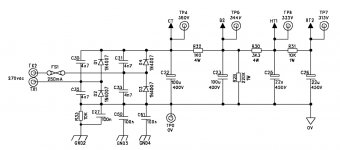
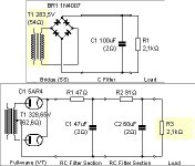
The amp is class a working 15W whith 2xECC83 and 2xL84.
I did the rectifier and the first capacitor and calculated the load to get 360 V like the first tap has in my circuit, after that I try with the same load an a rectifier tube (GZ34) to get 360V, But as it wasn´t as good signal as I could get whith the diodes, it wasn´t so smooth i just put as transformer a 300VAC and a RC filter beafore the first tap.
This way it works the same as the bridge rectifier even if I put more filters in both circuits.
THE PROBLEM is that if I chage the load the values change a lot from one to the other, and I don´t know if this will work.
Attachments
If your amp is running class A, then the draw on the power supply is very much constant, so I don't know what advantage the tube recto will provide.
You can't use a really big smoothing capacitor directly following a tube rectifier, so using a choke (5H - 10H) in place of the 91 ohm resistor would be a good way to reduce ripple.
Class A provides the ideal opportunity to use a tube rectifier, IMHO, because sag is not an issue so the stiff power supply offered by SS diodes isn't necessary (although proper filtering still is, of course). Compared with 1N4007 SS diodes, a tube rectifier would offer the advantages of low rectifier noise and a slow start.
If your amp is running class A, then the draw on the power supply is very much constant, so I don't know what advantage the tube recto will provide.
Class A provides the ideal opportunity to use a tube rectifier, IMHO, because sag is not an issue so the stiff power supply offered by SS diodes isn't necessary (although proper filtering still is, of course). Compared with 1N4007 SS diodes, a tube rectifier would offer the advantages of low rectifier noise and a slow start.
- Status
- Not open for further replies.
- Home
- Amplifiers
- Tubes / Valves
- power supply, Help please!!!