Hi Nelson,
This is a bit off topic, but have you ever considered designing a high-end headphone amp? Perhaps a version of your Super Symmetry circuit modified to drive headphone impedances?
This is a bit off topic, but have you ever considered designing a high-end headphone amp? Perhaps a version of your Super Symmetry circuit modified to drive headphone impedances?
Nelson Pass said:Naaaaw. I won't let Wayne spend that much money on 100V
Schottkys. He uses soft/fast recovery types most of the time.
Ahhh, here you go! Soft/fast recovery isn't the best, but it's good enough! 🙂
Actually, when working with linear power supplies, diodes are probably the least important factor. (That's not to say they should be ignored however)
Schottkys are usually in switching supplies, where you need the fast reverse recovery time with a low foreword drop. Think of a 3.3Volt 60Amp supply switching supply. With a 1 volt diode drop, that's 60W lost in diodes alone! Now, look at a 3.3Amp, 60Volt supply, same diode and only 3.3W lost in the diode. With low voltage output it pays to spend the $$$ on the Schottky... ...At 60Volts is becomes a little questionable.
Again, if you build a million of them, and save 50 cents on each one... 🙂
On linear supplies, I use what ever is cheap and big! 🙂
-Dan
icceman, could you tell me what I see at the first pictures? Where have you put the probe?icceman said:Difference between normal and schottky bridge rectifier:
An externally hosted image should be here but it was not working when we last tested it.
Normal rectifier
An externally hosted image should be here but it was not working when we last tested it.
Schottky rectifier
BTW: Very nice PS!


The measurements were taken from the - & + of the bridge rectifier (without load) and the scope was set to AC coupled. I didn't record down the time base (I'm using the AUTO function of the scope) as I'm not really interested in measuring anything (just wanted to see the difference between standard and schottky rectifier).🙂
AC traces
Even the trace with the Schottkys is a long way from a clean sine wave. How about posting the traces (standard vs. Schottky "downstream" from a pair of fairly conventional filter caps? That's what the amp or opamp will see.
I suspect that even with Schottkys (Freds, etc) that the a good PSRR shouldn't be neglected.
By the way, what is the typical set up to measure PSRR? I understand the idea and what it intends to show but I'm don't know how one goes about measuring it (especially with my meagre means).
Measurements.
Icceman, where and how did you take these measurements, I would like to compare some diodes I got in the same way.
Thanx.
icceman said:Difference between normal and schottky bridge rectifier:
Icceman, where and how did you take these measurements, I would like to compare some diodes I got in the same way.
Thanx.
Normal bridge rectifier module (not those fast recovery type).
Actually, I don't have a clue what those measurements mean, but theoretically schottky should sound better (no reverse recovery). I was also told that the sound quality of your amp depends greatly on your PSU, so I decided to use the schottky rectifiers with Nichicon Gold tune caps (300,000uF).
Actually, I don't have a clue what those measurements mean,
but theoretically schottky should sound better (no reverse recovery). I was also told that the sound quality of your amp depends greatly on your PSU, so I decided to use the schottky rectifiers with Nichicon Gold tune caps (300,000uF).Icceman, sorry to sound stupid, but did you just connect your probe across 1 of the diodes or over the 2 AC inputs, or where otherwise?
Thanx again.
Thanx again.
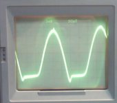
this is what i get with standart rectifier bridge with 1,2k load resistor, no cap, AC from sinewave generator. I´ll test one with schottkys later.
Re: Measurements.
The measurements were taken from the - & + of the bridge rectifier module(without load) and the scope was set to AC coupled.JDeV said:
Icceman, where and how did you take these measurements, I would like to compare some diodes I got in the same way.
Thanx.
The 4 Schottky rectifiers are in a bridge arrangement. The probe is connected across the + & - of the bridge (not the AC inputs).JDeV said:Icceman, sorry to sound stupid, but did you just connect your probe across 1 of the diodes or over the 2 AC inputs, or where otherwise?
Thanx again.
I don't think half-wave rectifying a signal from a function generator is much of a test. The reverse recovery characteristic depends upon the forward current. In equipment where the conduction angle is small and the current draw is large, like a power amplifier, the diodes have a much more difficult task.
Going crazy!!
Icceman, I apologise for asking questions which you already answered. My Internet is crazy over here. When I 1st asked you about how you tested, the last post was your's from 12-16-2002 06:09 AM. When I went backwards through the post just now, suddenly there are 10 more inbetween. Don't ask me how

Any way, now I got about 5 answers to my questions.
Thanx alot
Icceman, I apologise for asking questions which you already answered. My Internet is crazy over here. When I 1st asked you about how you tested, the last post was your's from 12-16-2002 06:09 AM. When I went backwards through the post just now, suddenly there are 10 more inbetween. Don't ask me how
Any way, now I got about 5 answers to my questions.
Thanx alot
jwb,
Thats absolute right, but it was all i´m able to put together in 5 minutes.
I´m on a better test setup right now.
real (big) transformer, rectifyer is bridge, not half. Please give your comment about should i use a capacitor or not, and how much load(i hope pure resistive)?
For test i have on hand a 400V25A normal bridge rectifier, a hand full of suber fast / soft recovery stealth diodes, and some 10 and 20A 100V schottkys.
I don't think half-wave rectifying a signal from a function generator is much of a test. The reverse recovery characteristic depends upon the forward current. In equipment where the conduction angle is small and the current draw is large, like a power amplifier, the diodes have a much more difficult task.
Thats absolute right, but it was all i´m able to put together in 5 minutes.
I´m on a better test setup right now.
real (big) transformer, rectifyer is bridge, not half. Please give your comment about should i use a capacitor or not, and how much load(i hope pure resistive)?
For test i have on hand a 400V25A normal bridge rectifier, a hand full of suber fast / soft recovery stealth diodes, and some 10 and 20A 100V schottkys.
till said:jwb,
Thats absolute right, but it was all i´m able to put together in 5 minutes.
I´m on a better test setup right now.
real (big) transformer, rectifyer is bridge, not half. Please give your comment about should i use a capacitor or not, and how much load(i hope pure resistive)?
For test i have on hand a 400V25A normal bridge rectifier, a hand full of suber fast / soft recovery stealth diodes, and some 10 and 20A 100V schottkys.
Sounds scientific!

I think you should try with a varying amount of capacitance. This will show the effect of conduction angle.
For the load, I would use a power FET mounted on a heatsink and a power resistor chosen for the desired current.
-jwb
- Status
- Not open for further replies.
- Home
- Amplifiers
- Solid State
- Power Supply Freds, Hexfreds, Ultrasofts, Ultrafasts and Fast Recovery