I am new to gainclone building and I want to get my feet wet. What I want to do is make one power supply and be able to make several amps, one at a time to add to this system. I would like to end up with at least a 5.1 or higher system, using different gainclone configurations for the different speakers.
I am using parts salvaged from an old power supply, and am unsure of some of their ratings.
I have a transformer that will output 20-25 vrms, or 28-35 V peak. It has different AC imputs, and I will put switches on them so that I can change the voltage on the fly. It is 5"*5"*6", not a torrid, and wound with heavy wire on the secondary, so I assume it will work.
My diodes are the type that screw into a metal heatsink, with one set going into the sink and another set coming out of the sink, which will give me two live heatsinks, one + and one -. The heatsinks for the diodes are 4"*3"*8.5" blocks of aluminum with fins.
I also have several 37,000uf 75V capacitors, so I thought two right after each side of the diode sink tied to ground would do it.
From here I was going to put some bolts which I would terminate my DC wires at. That way, I can run all my amps to one point in the PSU, thus making it easy to add or remove amps by just wiring the amps dc imputs to the bolt.
I want to mount this on a 16" by 16" piece of advantech plywood, and building a wooden case enclosing it.
Sorry I can't be more specific, but what do you think? I will post a picture of the parts as soon as I can get my camera memory card to cooperate.
The transformer should work. Don't bother putting switches, just use the primaries for your country, unless you're thinking of moving!
I'd stick with two of the 37,000uF caps. Any more will be putting immense stress on the bridge rectifier parts, and you will probably trip breakers.
Speaking of tripping breakers, you will need a "soft start" circuit for such large capacitance. This is a pretty simple circuit to do, but you should be comfortable working with mains wiring. I'd suggest something similar to the schematic shown at the bottom of this article:
http://sound.westhost.com/project39.htm
I wouldn't bother with the heatsink mounting diodes. Instead, get a pair of 35A 400V "GBPC" style bridges, and use those. They have the ability to be heatsinked (the bottom of a metal case will do) and are easier to handle.
What i'd go for is a similar setup to this:
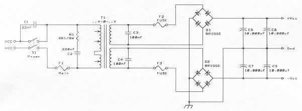
except instead of fusing in the transformer secondaries, i would put the fuses after the main capacitors - one set per amp.
I'd stick with two of the 37,000uF caps. Any more will be putting immense stress on the bridge rectifier parts, and you will probably trip breakers.
Speaking of tripping breakers, you will need a "soft start" circuit for such large capacitance. This is a pretty simple circuit to do, but you should be comfortable working with mains wiring. I'd suggest something similar to the schematic shown at the bottom of this article:
http://sound.westhost.com/project39.htm
I wouldn't bother with the heatsink mounting diodes. Instead, get a pair of 35A 400V "GBPC" style bridges, and use those. They have the ability to be heatsinked (the bottom of a metal case will do) and are easier to handle.
What i'd go for is a similar setup to this:
except instead of fusing in the transformer secondaries, i would put the fuses after the main capacitors - one set per amp.
Thank you for the heads up on the soft-start. Could you build a soft start without a relay? Maybe just have two switches, one with a high power resistor (like a light bulb) in series with the main? It would seem that that way, you could switch the switch with the resistor on and it would slowly charge the capacitors and after a second or two, you could turn the switch with the resistor off and turn the regular switch back on. I plan on hard wiring a couple cheap multimeters into the psu, so I can constantly monitor the voltage. Would this work or am I off in left field?
How much capacitance do I need to incorporate into each individual amp? Do I need to put some more huge capacitors right at the leads to the chip amps? I know I will need some smaller rated high quality caps there anyway. Does adding more capacitors hurt anything? I have 10 37,000uF's burning a hole in my pocket.
The reason I talked about the switching input on the transformer is that it has 100, 110, and 120 volt inputs. If I switched what input the main AC was going to, I could adjust the output DC voltage on the fly, like from 28 V to 35 V by just flipping a few switches. I have heard that different input voltages make the gainclones sound differently, and I would like to be able to adjust this on the fly to better compare.
Lastly, the reason I am using the fancy diodes with the heatsinks is that I already own them. Pulled them used out of a huge scrap PSU. That is also where I got the 37,000uF caps. I know they are probably very excessive, but I don't see the need to spend money to replace them with something else.
Thanks for your help so far!
Yes, you could. It is less comfortable and you always run the risk to switch wrongly or leave the switches for too long in the resistor position, creating an unstable condition for the amplifier.aardvarcus said:Thank you for the heads up on the soft-start. Could you build a soft start without a relay? Maybe just have two switches, one with a high power resistor (like a light bulb) in series with the main?
See? The regular switch must be turned on before the resistor is turned off. On the other hand there is no need to turn the resistor off, because it is bridged with the regular switch.aardvarcus said:after a second or two, you could turn the switch with the resistor off and turn the regular switch back on.
Depends on the amount of amps, the speaker load and your average SPL. You will find anything from 1.000 µF upward. One of those 37.000 µF capacitors per rail will probably do for most situations. As jaycee pointed out, more capacity puts more strain on the rectifiers and fuses (and transformer).aardvarcus said:How much capacitance do I need to incorporate into each individual amp?
No.aardvarcus said:Do I need to put some more huge capacitors right at the leads to the chip amps?
Hi,aardvarcus said:.... Could you build a soft start without a relay? Maybe just have two switches, one with a high power resistor (like a light bulb) in series with the main? It would seem that that way, you could switch the switch with the resistor on and it would slowly charge the capacitors and after a second or two, you could turn the switch with the resistor off and turn the regular switch back on.
don't use a light bulb.
The normal tungsten filament is PTC. You need NTC for this duty.
Use a Power Thermistor and you can then manage without a bypass. But, I recommend a bypass relay with a time delay of ~300mS. CL60 and similar do a good job if they are allowed to cool after every start up.
Extra smoothing capacitance is effectively a non issue until you get to near Farad levels.
I regularly fit +-45mF and also have +-60mF and +-75mF PSUs and none of these need any slow charging tweaks. The soft start for the 1kVA toroids does all I need and I can use a close rated T fuse.
1000VA will start and charge and run on a T3.1A and I don't suffer nuisance blowing.
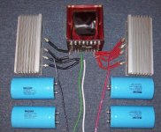
I got my camera to cooperate, so I attached a picture of my parts.
Thanks again for all the helpful replies.
I really don't mind flipping a few switches to turn the PSU on, I actually think it would be kind of cool. I could always upgrade to another setup in the future.
About what value of power resistor should I be looking at? Is there a site with a guide to calculate the value, or is there a generally accepted value? I would guess it has to do with the fuse and the capacitor I am using.
Also, what is a good place to study up on fuses? I was wondering if you could actually include a circuit breaker at the input? My house is on 20A breakers, but I was thinking of incorporating a 15A breaker into the psu.
Attachments
Get a large NTC Thermistor like AndrewT says. You can get them from old computer PSU's and also buy them online. You just put it in series with the transformer primary, no bypass switches needed, just regular on/off.
I used one on my 350W amp and I never blow the 6.3A fuse.
Also, the capacitors, are GREAT! Use as many as you like, the more the better. You can make the main Power Supply with all your 37,000 uf caps, then have small 1,000 uf+0.1uf caps for each amp (on the PCB near the chip) just to filter out anything picked up on the long wires.
Beefy caps = better bass, and less distortion!
aardvarcus said:Also, what is a good place to study up on fuses? I was wondering if you could actually include a circuit breaker at the input? My house is on 20A breakers, but I was thinking of incorporating a 15A breaker into the psu.
You could, but fuses generally react faster then breakers.
put a fuse on each power line pair for each amplifier to protect them. Put a fuse before the transformer(s?) with a slow start and obviously one in the power cord 🙂
I have my PSU partially assembled, using all 4 37000uf caps. I decided to test it without a soft start, and it never tripped a breaker, or messed with any of the other circuitry on the same breaker. I didn't have a fuse on it at the time, but have since gotten a 15 amp quick blowing fuse for it. It makes me wonder if I did it right... But anyway it developed +- 35.2 volts on the capacitors. I am just wondering if it will work right if I put a load on it. Could I test this with an incandescent light bulb? I was thinking about making a holder and wire it across the rails to neutral to test the voltage regulation under load. I really want to make sure this power supply is good before I finish it out completely.
- Status
- Not open for further replies.
- Home
- Amplifiers
- Chip Amps
- Power Supply For Multiple Amps