Hello everyone
I’ve been working on a smps for a car amp
I’m using a core from “magnetics (mag-inc.com)” part # ZW44916TC
Outside diameter 49 mm, inside diam. 33 mm hgt. 15 mm
I’m using 3-0-3 turns on the primary with 4 strands of #18 wire
Secondary => 2 strands of #15 wire in parallel, 12 turns
The best result I’ve gotten so far is 74% efficiency at 30 watt output , frequency 50 KHz
But when I increase the load, the efficiency drops to 54% the mosfet temp increases and core and winding temp remains the some “ cool”
I’m using an angle grinder and a sanding machine as the load
The mosfet are 4 IRLR3410TR on each side.
Is this normal???
I’ve tested the supply at the following frequencies 92 KHz., 77KHz, 50KHz, and 31KHz
The waveform at drain are symmetrical, turn on and turn off time remain the same
Any help will be very much appreciated.
😕
in my neophyte opinion-
1. what is your duty cycle and/or dead time?
2. skin depth, the frequncies that you are using may not be utilizing the wire well with some high surface currents;
without going through all the math
i found a couple of skin depth calculators that seem close.
http://www.bcae1.com/trnsfrmr.htm
and
http://daycounter.com/Calculators/SkinEffect/Skin-Effect-Calculator.phtml
3. are your loads ac or dc or universal motors?
4. what are your inductor specs
That sounds like either transformer saturation or a gate drive problem. Both issues are very layout dependent so could you post schematics, pictures, pcb design...??
Also you should check MOSFET drain waveform at turn off (oscilloscope at 200ns/div or so). The spike that you are going to see is a good indicator of the current that was being conducted just before turn-off. When the transformer is saturating one drain shows a much taller spike than the other, while a nicely balanced push-pull circuit shows equal spikes.
Also you should check MOSFET drain waveform at turn off (oscilloscope at 200ns/div or so). The spike that you are going to see is a good indicator of the current that was being conducted just before turn-off. When the transformer is saturating one drain shows a much taller spike than the other, while a nicely balanced push-pull circuit shows equal spikes.
Hi jamesrnz
The links are very helpful.
I normally work on the project on weekends, so please forgive any delayed response.
The info you requested are as followed
Duty cycles approx. 30% on each side
The loads are universal motors and the output is DC , the diodes are ultra fast.
O.D. (A) 44.60 mm
I.D. (B) 34.80 mm
Ht. (C) 16.85 mm
Ae 120mm2, le 127 mm, Ve 15298 mm3
The material is W
Permeability 10000 tolerance 30%
Data sheet is at http://mag-inc.com/pdf/Ferrites/2006_Materials_W.pdf
And this company supplies samples very easily. Just call them.
One measurement I did not make is , the voltage drop across the mosfet during the on time. I think that the reason for the heat generated by the fets is directly related to the power wasted by the fets during increased load.
What do you think is an acceptable efficiency for such a psu???
I will keep you posted.
Thanks again
Transformer Primary Turns
Shiraz-
What equation did you use for calculating your primary turns? At what frequency is the rated permeability of 10,000m measured?
If the permeability of 10,000 is measured at, say, 50kHz, with the following equation,
N(pri) = Vin (min) x e^8 / [K x F(sw) x A(e) x B(max)]
= 11 x e^8 / (4 x 50,000 x 1.2 x 10,000) = 2.18
you should have 2.18T +2.18T for the primary,
where Vin(min) = 11V;
K = 4;
F(sw) = the switching freq.
1.2 = the crosssectional area in cm^2;
and 10,000 = the permeability at 50kHz.
I would check the Magnetics datasheets for the "W" material to extrapolate what the B(max) is at the different frequencies. As your chosen frequency goes up, your B(max) will go down, though not at the rate for all materials. I seem to recall looking at the graphs for Amidon's "W" material, but I don't recall any hard numbers.
Anyway, check this out to see if this reduces core saturation that Eva mentions, and also look at the thickness of the wires for all your windings. Using more strands of thinner wire guages will significantly reduce the skin-effect that Jimbo mentions.
Hope these suggestions help.
Cheers,
Steve
Thanks for your help Eva
I’m currently at work so schematics will be posted later on.
Here is a brief description of the circuit
I’m using a TL 494
The output of the chip is inverted by two mosfet and then fed into an H bridge which drives the 4 + 4 mosfet. i also used mosfet for the H bridge. The waveform at the gate of f the 4+4 mosfet is reasonably clean. The output of the H Bridge is capable of driving low impedance load. So it charges and discharges the gate fairly fast.
Thanks for the tip on spikes.
Hi n-channel
I went a different way
I used the following equation in an excel document
Flux density = Bpk=E*10^8/4*Anf ,
=(12*(10^8))/(4*(1.18*3*50000))
1694.915254 gause
Then I used this flux density in the chart supplied by mag-inc.com
To calculate what loss I will have at 50 KHz.
Approx. 118mW/cm^3 , core volume is 15 cm^3
118 *15.298cm^3= 1805.164 mW=1.8 watt
Is there something wrong with this way?
And I like your equation, but I have one question:
= 11 x e^8 / (4 x 50,000 x 1.2 x 10,000) = 2.18
What is “e”
Thanks for your support.
e is the exponential. So, I f I say 11e8, I mean 11 x 10^8. It's just shorter notation. Also, I use 11v as the minimum V(in) to account for low voltage and to give a little headroom for regulation.
This leads to the next question: Are you running the TL494 in true PWM fashion for regulated +/- outputs, or are you running it WOT (wide-open throttle) for no regulation with minimum deadtime?
Ok, I understand the permeability is 10K at 50kHz, but the B(max) at 50kHz is 1694G. I mistakenly plugged in the permeability for the B(max) to get the 2.18T + 2.18T.
I should have plugged in the 1694G. So the re-calculated equation should go something like this:
N(pri) = 11e8 / [4 x 50,000 x 1.18 x 1694] = 2.751T. You would just round this up to 3T + 3T.
Hi N-Channel
Thanks again for your response. I value your advice and support greatly.
It’s a really easy way to determine the best pri. Turn for a specific core.
Currently the psu doesn’t have regulation, so it’s running at 30% duty regardless of output voltage and output current.
Thanks again for your response. I value your advice and support greatly.
It’s a really easy way to determine the best pri. Turn for a specific core.
Currently the psu doesn’t have regulation, so it’s running at 30% duty regardless of output voltage and output current.
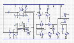
This schematic is not complete. Note that pin 1 and pin 16 are not connected. I’ll post the completed version as soon as I can.
I’ve measured the spike at the drain of the mosfets as Eva suggested and they are equal on both sides. I also measured the gate wave form, I noticed that there are considerable spikes on the gate of one transistor when the other switches on.
I paralleled 4 mosfet on each side with individual gate resistors. Please for five my transformer symbol .
Attachments
- Status
- Not open for further replies.
- Home
- Amplifiers
- Power Supplies
- Power supply efficiency