For my Aleph-JX I use per channel two transformers (Amplimo 2x18V) and four recifier bridges.

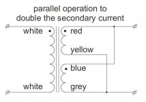
First I wanted to parrallel the secondaries as within this picture;

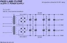
But then I saw the following schematic of a pass labs power supply;

I haven't seen this way of connecting before and I don't understand it well. Do the phases of the secondaries need to be out of phase with each other or is this possible with just any kind of transformer?

First I wanted to parrallel the secondaries as within this picture;

But then I saw the following schematic of a pass labs power supply;

I haven't seen this way of connecting before and I don't understand it well. Do the phases of the secondaries need to be out of phase with each other or is this possible with just any kind of transformer?
That is slightly unusual but tying center taps to the neutral cuts the rail voltage in half and I imagine doubles the available current. I'll have to stare at it for a while.
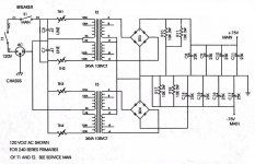
Is it me or is there a diode drop away from a short when A swings negative relative to 0? Could it be a drawing error?
I think the center taps are being held at 0 by the interconnection of the trafos. Does that make sense. It's a little hard to get my head around.
I see a short from T2 secondary terminal 0 the CT connection between T2 and T3 to the Neutral line, to the negative terminal of BR3, through the lower left diode to T2 terminal A. That's the easiest to see, but the 50% duty cycle short exists for all windings.
Maybe NP will chime in and set us straight.
Maybe NP will chime in and set us straight.
Yeah, I could see that after you brought it up. Either we're dummies or the dwg is in error. I'm going to stare at it a while longer.
That R17 is shortened is my mistake. I have edited the schematic and removed the part that was not relevant, because I don't want to publish the original schematic here.
The only way I can see it working would be reversing BR4 and disconnecting both BRs from the ground, and taking ground solely from the tied center taps. You eliminate a diode junction from the circuit, doubling the thermal capacity of the bridges. You can do the same thing using just 2 diodes for each trafo but the bridges give you a nice package to bolt to the chassis for cooling.
NP has warned in the past about using the service manuals for construction.
NP has warned in the past about using the service manuals for construction.
- Status
- Not open for further replies.
- Home
- Amplifiers
- Pass Labs
- Power supply connections