Amateur Audiophile please be gentle.
I have downloaded PSUD2 and experimenting with component values of CLC power supply for RH84 SE amplifier. Am looking for ideal values to aim for. Being noob I dont know how much ripple amplitude will be OK or such things. My Secondary supply is 0-250V separate for each channel. I have tried various Capacitance value after secondary; various choke values and am getting 2mV to 10mV (Third column in the PSUD2 software).
Best would be if you can give straightforward component values for two capacitors and choke (current and ohms ratings) as I dont want to go overboard but still have more than enough margin to be safe for my first build.
Secondary unrelated question is
RH84 amp blog says output transformer of 5k-6 K primary and 8 ohms speaker load. A friend here has 7K primary and 8ohms secondary.. Will that work ? My speaker choices would be limited and probably comparatively I will get little less power output and little stress (?) on output valves if volume increased ?
thanks and regards
Last edited:
Hiten,
Many 8 Ohm rated speakers have a minimum impedance of 6 Ohms, often in several frequency ranges.
A 7k to 8 Ohm transformer that has a 6 Ohm load impedance, is 5,250 Ohms on the primary. Pretty close to 5,000 Ohms.
Take your Ohmmeter and read the speaker DCR. Is it about 6 Ohms?
Example possible speakers:
A two way 8 Ohm rated speaker with closed box might be 6 Ohms from 20-40Hz, 6 Ohms from 200-400Hz. It might have peaks of 25 to 50 Ohms at bass resonance (perhaps 60Hz), and 16 to 20 Ohms at the crossover frequency (perhaps 1.5kHz).
A two way 8 Ohm rated speaker with ported box might be 6 Ohms from 20-30Hz, 6 Ohms at port resonance (60Hz perhaps), and 6 Ohms from 200 to 400 Hz. It might have peaks of 25 Ohms at 40Hz, and at 80Hz; and 16 to 20 Ohms at the crossover frequency (perhaps 1,500Hz).
Your speaker may vary.
Do not worry too much.
Have fun building, and enjoy listening.
Last edited:
thanks 6A3sUMMER,
pardon me for not saying in first post. I would be using single wideband driver.
pardon me for not saying in first post. I would be using single wideband driver.
How much ripple? Good question, not easily answered, like with a lot of things it depends, it depends on how sensitive you are to hum,the PSRR of your OP stage etc, but in a nutshell get it as low as possible without making the PSU a possible contributor to instability and without overheating or putting strain on the mains tfmr, smoothing caps etc.
Andy.
Andy.
Hiten,
An example of a single full range driver in an open baffle or in a closed box:
The impedance might be equal to DCR from perhaps below 20Hz to 40Hz, and then rising to a maximum at the driver resonance, perhaps 60Hz. Then the impedance will fall again to DCR from perhaps 200 to 400Hz. Then the voice coil inductance will cause the impedance to continually increase all the way to 20kHz.
A full range driver in a ported box typically has low impedance at 3 different frequency ranges, and 2 peak impedances, one at either side of the port resonance.
Again, the low impedance can dip down to the DCR of the voice coil.
But if you designed your own single driver full range speaker, you probably already looked at the free air driver impedance curve, and know all of that.
Last edited:
6A3sUMMER that info would be helpful to me in future. thanks
---
My hearing is not good. Dont know PSRR of RH84 amp. This is just my learning build. As I already have valves and sockets and PT with me.
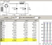
here is some rough fiddling with PSUD. See attached pic. and yellow highlighted data. Would this be ok ? There ought to be some ball park figures for powersupply Capacitor and choke values. going overboard can be counterproductive ? atleast tell if both C1 C2 should be same ? or lower value at transformer side ? Choke value would also probably some specific value (for this RH84 amp only) Going for higher value would have deminishing return. isn't it? give some clues and guidelines.
Original RH84 had only 47uf-10H-200uf. 200uf aftter transformer will have detrimental effect on choke ? Choke had 100mA capacity for both channel. So can I get away with 50mA per channel for my dual separate amp ?
thanks
---
My hearing is not good. Dont know PSRR of RH84 amp. This is just my learning build. As I already have valves and sockets and PT with me.
here is some rough fiddling with PSUD. See attached pic. and yellow highlighted data. Would this be ok ? There ought to be some ball park figures for powersupply Capacitor and choke values. going overboard can be counterproductive ? atleast tell if both C1 C2 should be same ? or lower value at transformer side ? Choke value would also probably some specific value (for this RH84 amp only) Going for higher value would have deminishing return. isn't it? give some clues and guidelines.
Original RH84 had only 47uf-10H-200uf. 200uf aftter transformer will have detrimental effect on choke ? Choke had 100mA capacity for both channel. So can I get away with 50mA per channel for my dual separate amp ?
thanks
Attachments
....give straightforward component values for two capacitors and choke (current and ohms ratings) as I dont want to go overboard but still have more than enough......
Why are you asking here? Read every schematic you can get your eyes on. ESPECIALLY commercial products which had to satisfy many people or the designer would be out of work.
While supplies for "same as you want" (say two 6V6 in stereo) are good, you can allow for mono (half) or 6L6 (double) etc.
PRR
regards
I dont understand. Please tell if anything is wrong."Why are you asking here?"
regards
I
Anyhoo, don't worry about it, most of us don't bite and a kick up the backside is good for us sometimes.
Andy.
I think PRR is being a bit grumpy but also makes a valid point; if someone works out the values for you(quite a bit of work) you'll have learned nothing. Using the old "I've got a problem wot someone has probably come across before and solved" maxim, looking at other schematics of amps similar to yours is a good way of solving the issue. Your request for someone to solve your problem could be construed as lazyness, and if someone hadn't had their morning coffee or had had a row with the missus, a friendly kick up the arsenvenga might be forth coming , just musing aloud here....dont understand. Please tell if anything is wrong.
Anyhoo, don't worry about it, most of us don't bite and a kick up the backside is good for us sometimes.
Andy.
You can learn more about PSUD by reading a guide by DHTROB.
https://www.dhtrob.com/overige/pdf/dhtrob_psu.pdf
ray
https://www.dhtrob.com/overige/pdf/dhtrob_psu.pdf
ray
Your request for someone to solve your problem could be construed as lazyness,...
Anyhoo, don't worry about it, most of us don't bite and a kick up the backside is good for us sometimes.
I just thought the native wildlife was hibernating 😀
It took me a while to 'get' to get to what extent that it's DIY.. you do it, people may comment or help but don't expect it. I prefer to think of it as - you're doing it anyway.. 🙂
I may have been doing a shed load of modelling, annoying people with the ideal, but through that and reading.. I've learn a lot. However it's unstructured learning so there's probably big holes in the subject matter.
6A3sUMMER that info would be helpful to me in future. thanks
---
Original RH84 had only 47uf-10H-200uf. 200uf aftter transformer will have detrimental effect on choke ? Choke had 100mA capacity for both channel. So can I get away with 50mA per channel for my dual separate amp ?
thanks
my last build / EZ-81 - 100uF - 10H - 100uf
.... point; if someone works out the values for you(quite a bit of work) you'll have learned nothing.....
I approve of learning. But I can also approve of taking known-good values without much further thought. Most 'new' designs are VERY similar to designs which came before.
The question of ripple in an SE amp is non-trivial. But frequently you do better with clever leverage than brute force lumps. Multiple C sections. Separate screen filter.
I converted an old console stereo to RH84, and used 47uF --> choke --> 200uF similar to what the OP is simulating. That worked fine (choke value unknown). I would suggest go with that, you could leave room to add another cap later if you're worried about it.
sorry to reply late.
I understand you guys. Thanks everyone.
Being newbie I was curious since logically thinking if small value cap is first (Lets say just below workable) how will it affect choke and transformer with view that it will be as good as LC filter (instead of CLC) and transformer will be stressed (?).
May be some otherday.Will go with values and see how it goes. Need to order chokes.
Thanks again and best wishes
- Home
- Amplifiers
- Tubes / Valves
- Power supply CLC values (PSUD)