Here is an article I put together about how to deploy proper power supply bypassing capacitors to op amps and split supply circuits.
Types / values / dielectrics / and voltage coefficients are all discussed. What do you guys think? Agree? Disagree? Looking for any feedback or insights that were maybe not mentioned or touched on. Here is the article -
https://sparkoslabs.com/power-supply-decoupling-capacitors/
Types / values / dielectrics / and voltage coefficients are all discussed. What do you guys think? Agree? Disagree? Looking for any feedback or insights that were maybe not mentioned or touched on. Here is the article -
https://sparkoslabs.com/power-supply-decoupling-capacitors/
Attachments
"So now that we understand that we need to use 0.1uF capacitors from each power rail to ground" - sorry I must be dense, I still don't understand. You said so, but where are the arguments? Why do we need them, why 0.1uF??Here is an article I put together about how to deploy proper power supply bypassing capacitors to op amps and split supply circuits.
Types / values / dielectrics / and voltage coefficients are all discussed. What do you guys think? Agree? Disagree? Looking for any feedback or insights that were maybe not mentioned or touched on. Here is the article -
https://sparkoslabs.com/power-supply-decoupling-capacitors/
Jan
Because all op amp datasheets say that they are required for stability. 0.1uF is the typical value that gets recommended, though the exact value is not quite as important.
They must go from each rail to ground because the load is normally grounded, and the input is also referenced to ground, and that is how the load current flows go (to ground)
They must go from each rail to ground because the load is normally grounded, and the input is also referenced to ground, and that is how the load current flows go (to ground)
I'm not so sure it works as a 'one size fits all' article tbh
Decoupling an opamp close to the pins with a single cap or a cap + series R depending on the application would be something I would always do. I know that saying to decouple into the ground from each rail can cause problems with injection of noise from the PSU is an argument that is often trotted out but I can tell you it is a real problem in some situations.
You have to look at each case on merit but I think it wrong to discount the single decoupling cap across the supply.

Well Doug Self disagrees and that's suggestive as he has a lifetime's experience. He specifically recommends high frequency decoupling be from rail to rail and avoid injecting noise into the signal ground. High frequency decoupling is about stability of the opamp (which doesn't have a ground connection).What do you guys think? Agree? Disagree?
So my vote is against you and for Doug Self's meticulous research and design experience.
Just to be clear both rails do need bulk decoupling to signal ground to prevent unwanted feedback between stages, but the requirements of stability with modern fast opamps only require a 100nF ceramic between the supply pins close to each opamp in most cases, just like any other high speed circuit.
Or put another way there are several functions of decoupling and you don't realize this.
The fact that you worry about the linearity of decoupling caps (Y5V v. X7R v. C0G) is indicative - the only worry that's valid is microphony of ceramics - non-linearity in decouplers is of no concern at all as they don't carry signal.
Film capacitors are often too inductive for high speed decoupling and could actively contribute to instability in a high speed amplifier circuit by adding inductance.
Also your circuit diagram lacks any bulk electrolytic decoupling which isn't wise for audio frequency use.
So basically most of your article is BUSTED as flawed speculation without basis in fact or experiment I think.
[ or do you have detailed research on these issues that refutes Doug's lifetime's experience? ]
Last edited:
Well I consider myself a student of Doug Self as well. . 🙂
And yes, some of these points are valid when we look beyond the scope of the article, and I realize that its hard to make a "one size fits all" approach.
While op amps do not have a dedicated ground pin, the load current in split supply applications usually flows to ground as does the feedback current in the non inverting configuration.
I did mention bulk decoupling with ceramic and electrolytic or tantalum which is a good idea when higher load currents are involved.
Its true that bypass caps can possibly inject noise into a ground system, which one would use star routing and clean supplies to combat against. I felt that going deep into the layout of these things, and discussing things like self resonant frequency was beyond the scope of the article. It was intended to be geared towards audio and low-speed (few hundred KHz) type op amps and circuits.
RF and high speed is a totally different game.
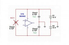
Also, as the article points out, there is inherently a cap "across the rails" as the two caps from each rail to ground are effectively in series. So whether that cap is required or not - its inherently there. I was just suggesting that if one ONLY puts one cap across the rails (and not from each rail to GND) that they bypassing has not been done correctly.
I have most of Doug Self's books, do you know which one (and where) he discusses this?
And yes, some of these points are valid when we look beyond the scope of the article, and I realize that its hard to make a "one size fits all" approach.
While op amps do not have a dedicated ground pin, the load current in split supply applications usually flows to ground as does the feedback current in the non inverting configuration.
I did mention bulk decoupling with ceramic and electrolytic or tantalum which is a good idea when higher load currents are involved.
Its true that bypass caps can possibly inject noise into a ground system, which one would use star routing and clean supplies to combat against. I felt that going deep into the layout of these things, and discussing things like self resonant frequency was beyond the scope of the article. It was intended to be geared towards audio and low-speed (few hundred KHz) type op amps and circuits.
RF and high speed is a totally different game.
Also, as the article points out, there is inherently a cap "across the rails" as the two caps from each rail to ground are effectively in series. So whether that cap is required or not - its inherently there. I was just suggesting that if one ONLY puts one cap across the rails (and not from each rail to GND) that they bypassing has not been done correctly.
I have most of Doug Self's books, do you know which one (and where) he discusses this?
All analogue design I see has caps to the 0V supply, usually a plane, I can only think of 1 design out of many hundreds that has a cap across the supply. Most designs will have a 0.1 SMD next to the supply pin down to 0V and usually a larger SMD cap in parallel. Many design these days may have a 100pF next to the pin, with the 0.1uF next to that one. For the best performance a ground plane is best.
Texas etc. have many design notes regarding decoupling of op-amp's. all recommend a cap down to 0V's...
Texas etc. have many design notes regarding decoupling of op-amp's. all recommend a cap down to 0V's...
- Home
- Design & Build
- Construction Tips
- Power supply bypass caps - how and what