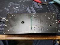
Simple question, should all the standoffs be electrically connected to the case or just one standoff and put the earth ground at that location. I'm thinking the last.
The picture shows a modified single rail power supply board with all four standoffs connected to the ground of the power supply and through the standoffs, to the case.
I'm thinking I should cut the traces to three of the standoffs and just leave the upper right one connected to the supply ground and connect my earth there also.
View attachment 995775
There should only be two internal electrical connections to the chassis.
First, the IEC safety ground goes directly to the chassis with a dedicated bolt, lockwasher, and nut.
Second, from only one point of the audio circuit/power supply. (Guitar amplifier builders often ignore this.)
Sometimes an impedance is inserted in this connection (diodes, resistor, capacitor).
First, the IEC safety ground goes directly to the chassis with a dedicated bolt, lockwasher, and nut.
Second, from only one point of the audio circuit/power supply. (Guitar amplifier builders often ignore this.)
Sometimes an impedance is inserted in this connection (diodes, resistor, capacitor).
Last edited:
That pcb looks like very bad practice, is that for a guitar amplifier perhaps?
Guaranteed to cause multiple ground loops.
Guaranteed to cause multiple ground loops.
- Home
- Amplifiers
- Power Supplies
- Power Supply Board ground loop question
