Hi guys. I am a beginner and I have a (stupid??) question and need help.
Still working on my first tube amp build. The first cap after the bridge rectifier is as per project 100 microfarad. I have in house a 450 microfarad same voltage rating. Can I use it? What shall be the impact on the sound quality with a bigger capacitance?
Tks for help")
Still working on my first tube amp build. The first cap after the bridge rectifier is as per project 100 microfarad. I have in house a 450 microfarad same voltage rating. Can I use it? What shall be the impact on the sound quality with a bigger capacitance?
Tks for help
There is no advantage , with valve amplifiers, to use such a high value.
Consider slid state amplifiers on this forum where people 'modify' the smoothing capacitors to very high values and wonder why their mains transformers fail.
If your valve amplifier has a valve rectifier, the cathode will be damaged everytime you turn it on until it goes low emission and strips itself.
Check the valve for maximum tank values.
Hi Jonsnell
Understand you do not agree with use of bigger cap however as beginner I like to understand
The schematic I am using do not have a valve rectifier. the layout is transformer ,bridge rectifier ,smoothing capacitor.
So as you said before the only part that may actually suffer is the bridge rectifier and may be the main transformer due to the high in rush current?
So assuming I may use decently sized or oversized transformer and bridge rectifier there should be no hardware fault and a bigger capacitance should help in reduce the ripple that so far I am aware may affect the sound quality. On the other hand such big capacitance could affect the sound in other way. I was very impress on the huge change a simple coupling caps change may have.(I changed a low quality PP coupling cap with an high quality and trust me was like to change ampli)
Now this is a power supply capacitor don't' think the change shall be so dramatic. In any case I guess the only way to make up my mind with my limited knowledge is to give a try. Tks again
Hi JM
Just see you post
Yes I know 20 amps is a bit overkill but I work in industrial environment and I have access to some of those component Also the main transformer is a strange oversized beast but trust me they are more than sufficient for a small ampli. Actually I believe some of those "audio" grade component offer much less for much more money.
In any case I still would like to know the possible effect of a bigger capacitance on the power supply in a such audio application
A larger reservoir capacitor can mean bigger but shorter charging pulses, which can increase induction coupling and grounding problems. However, beyond a certain size the charging pulses are limited by things like transformer resistance and inductance so the pulse problems don't get any worse as you go from too big to ridiculously too big. You may have problems with start-up currents blowing fuses, so may need a soft-start circuit which would not be needed with a more sensible size cap.
This all assumes a silicon rectifier. If you are ever tempted to use a valve rectifier then you may be limited to 50uF as the first cap.
This all assumes a silicon rectifier. If you are ever tempted to use a valve rectifier then you may be limited to 50uF as the first cap.
Since nobody has mentioned it so far, you should download PSUD2 and model your proposed power supply.
PSUD2
There are many conflicting ideas about how to design a power supply. If you have the time and patience, it should help to model a supply and then listen to how it sounds.
It will help you to study power supplies from other people's amplifiers. Most of them would not use a 450 uf cap, particularly directly after the rectifier. Model in PSUD with much lower values, even well below 45 uf. Learn how to use the step load feature which will show you how your supply copes with a change in demand.
You might also consider motor run caps and DC Link caps instead of electrolytic caps. They are usually considered to sound 'better', though the motor runs are physically large. However, they often come with higher voltage limits than the 400 - 450 volt limits of electrolytics which can be really useful.
ray
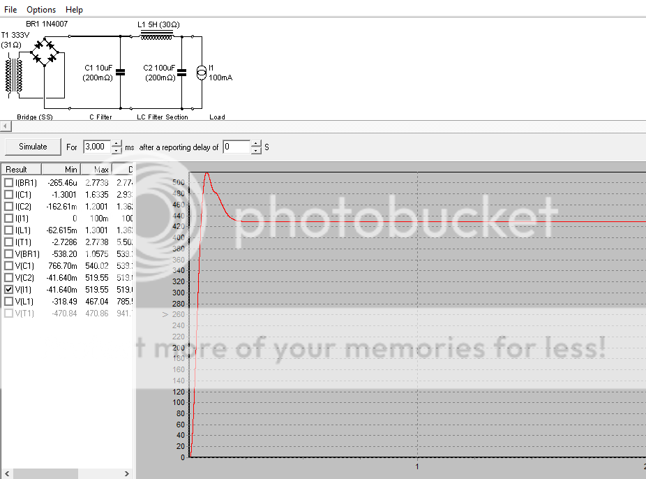
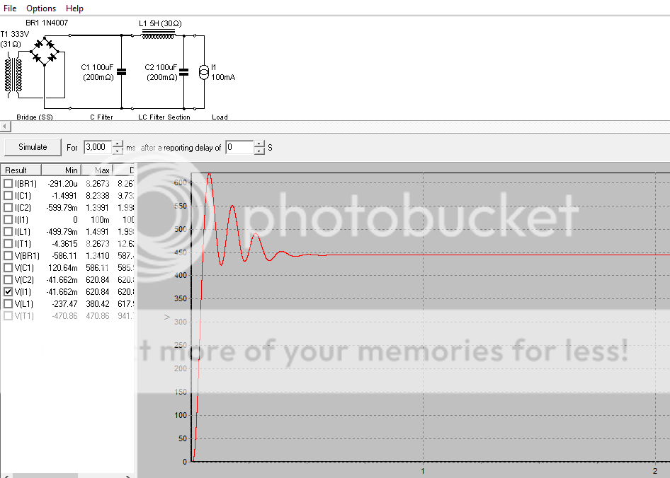
To give you an idea of what PSUD can do, here are three samples where the first capacitor is 10 uf, 100 uf and 450 uf. Note the ringing increases with the increase in value which I understand is considered to be undesirable.
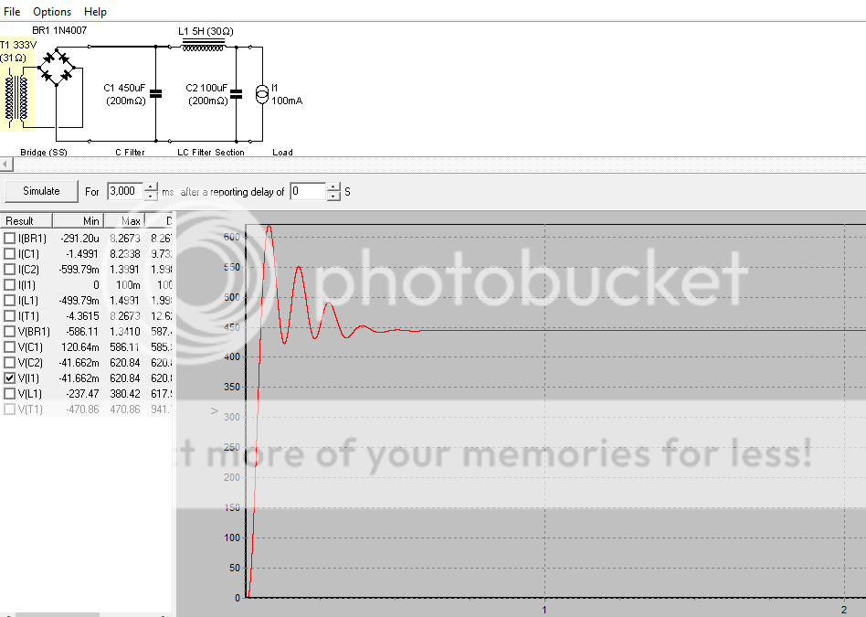
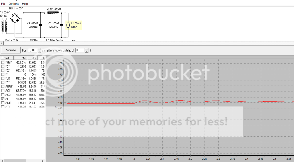
Below we zoom in on the 450 uf waveform.
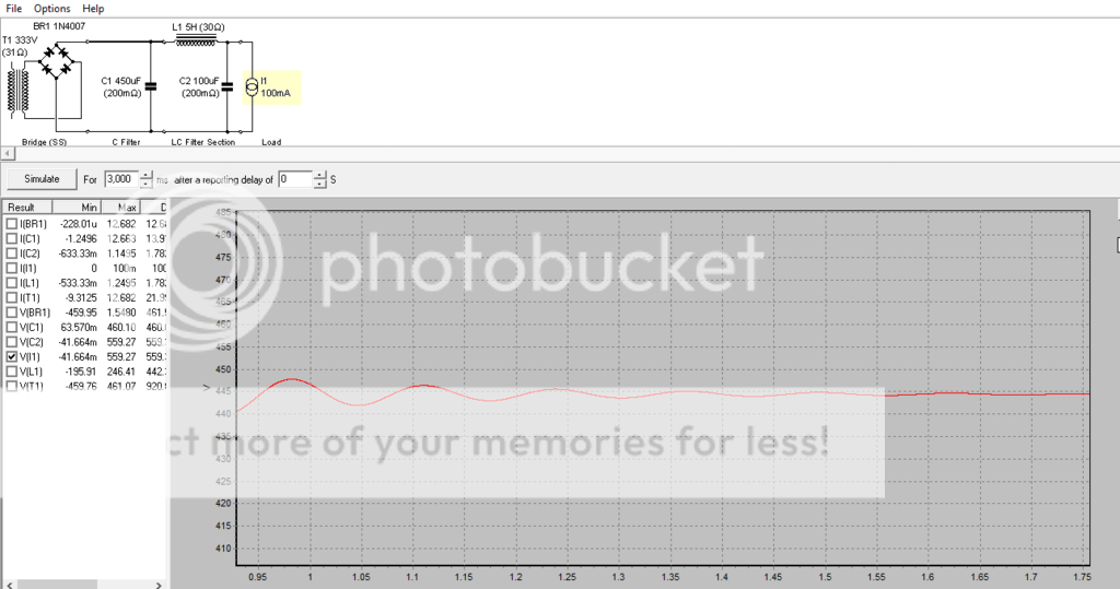
Below we set up a stepped load.
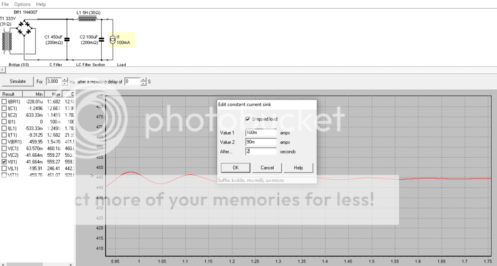
Finally we can see the results after 2 seconds when the load changes from 100 ma to 90 ma and we see ringing.
There are lots of examples out there. Try to become familiar with this very useful program.
ray


Below we zoom in on the 450 uf waveform.

Below we set up a stepped load.

Finally we can see the results after 2 seconds when the load changes from 100 ma to 90 ma and we see ringing.

There are lots of examples out there. Try to become familiar with this very useful program.
ray
Ok Guys Tks
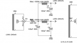
All is very useful ,appreciate all your help. I shall download psud and try to simulate thought I believe shall take some time before I can actually do anything with it. In any case I attach my psu schematic as you can see nothing special there is also a further RC section on the line going to the pre section (one per channel) always using 100 microF.
Appreciate any comment. Also at this point if I decide to increase to 450 microF should I change only the first cap ? should I change the last ? or should I change all of them?
As I am learning here one more question. Are those Caps to be polarized electrolytic capacitor or NP and other type can be used as well?
Attachments
I thought this thread was about the first (reservoir) cap? The second (smoothing) cap is quite different. Do you understand the quite different role played by these two caps?Appreciate any comment. Also at this point if I decide to increase to 450 microF should I change only the first cap ? should I change the last ? or should I change all of them?
They don't have to be polarised. Electrolytics are the smallest and cheapest option, and perfectly adequate for this purpose.As I am learning here one more question. Are those Caps to be polarized electrolytic capacitor or NP and other type can be used as well?
One way to look at caps in PSUs is to calculate the stored energy:
W =1/2*C*V^2
(Looking at a simple SE-amp, say EL34 at 8W and compare to something very transistor-ish of the same wattage will propably show that we add much more Farads to our tube amp than is added to transistor amps.)
Capacitance is lite vitamin C, it makes sense up to a certain level, but adding more serves no purpose at all.
I even think there's a thumb of rule how many Joules are recommended per oitput Watt.
Hi DF96 .Thank you for replay.As I said I have limited knowledge and I am trying to learn however it is my understanding that the first capacitor (reservoir) is to accumulate sufficient energy to respond to sudden load change while the second (smoothing) should serve more as noise cleaner?
Nevertheless they are on the supply path so in regards the impact on the sound quality they should be considered as well?
What your advice at this point I am curios to listen sonic difference so I am going to change the first cap and see what happen. Should I change also the smoothing caps or that is not necessary.
Appreciate your clarification on the use of different type of caps other than polarized electrolytic
To answer to Welcome regarding the 450/470 microF value ..well I do not remember! I am out for work now and I cannot check I just spot those in the part box so I start to think to use them anyway either 470 or 450 don't' think change so much as long they are efficient as you say. Thanks for replay
Yes, something like that. The first cap stores charge and so can supply the amp when the rectifier diode has switched off. The second cap acts with the choke (or resistor) to form a low pass filter to reduce ripple.As I said I have limited knowledge and I am trying to learn however it is my understanding that the first capacitor (reservoir) is to accumulate sufficient energy to respond to sudden load change while the second (smoothing) should serve more as noise cleaner?
Both will affect ripple i.e. hum/buzz. The first cap affects sag/droop by setting the low frequency (subsonic down to DC) output impedance of the supply. As far as audio signal is concerned the rest of the circuit really only sees the second cap, but modified by the choke - which is where the PSUD2 ringing comes from.Nevertheless they are on the supply path so in regards the impact on the sound quality they should be considered as well?
Yes, something like that. The first cap stores charge and so can supply the amp when the rectifier diode has switched off. The second cap acts with the choke (or resistor) to form a low pass filter to reduce ripple.
Both will affect ripple i.e. hum/buzz. The first cap affects sag/droop by setting the low frequency (subsonic down to DC) output impedance of the supply. As far as audio signal is concerned the rest of the circuit really only sees the second cap, but modified by the choke - which is where the PSUD2 ringing comes from.
HUmmmm need some time to digest this

So recap
the first capacitor is more for the quantity so as long it has a sufficient capacitance it should be fine and in any case if I increase to 470 should not have a negative effect
As the circuit at this point only see the second cap it pop in my mind those should be the best possible quality and with sufficient capacitance. Hence I need to learn how to use PSUD
Tks all guys
Here are some screen shots using the values from the schematic. It should be pretty close even though the transformer ohms are probably wrong.
The first shows your existing situation. Note that the stepped load gets back to a stable state quicker than the next two options.
 [/URL][/IMG]
The next shows the 100 uf before a 450 uf. Note how much longer it takes to get up to the operating voltage.
 [/URL][/IMG]
The final shows the order reversed. Note the ripple in the stepped load area.
 [/URL][/IMG]
Try to replicate these diagrams and then play around.
ray
The first shows your existing situation. Note that the stepped load gets back to a stable state quicker than the next two options.
The next shows the 100 uf before a 450 uf. Note how much longer it takes to get up to the operating voltage.
The final shows the order reversed. Note the ripple in the stepped load area.
Try to replicate these diagrams and then play around.
ray
- Status
- This old topic is closed. If you want to reopen this topic, contact a moderator using the "Report Post" button.
- Home
- Amplifiers
- Power Supplies
- Power suply capacitors change