Hi y'all!
I'm currently working on a system that to my knowledge has not been done before.
With a high-speed ADC from Maxim I am sampling both output current and voltage. Regarding the phase angle of probably non-resistiv loads I am using more than 1MS/s and multiplying worst case voltage and current every 1/50k seconds.
Pros:
1: Active over-current protections circuitry (driving a relay)
2: Active No-DC protection circuitry
and finally
3: Active Over-Wattage protection circuitry. Programmable limit controlled via uP and remote control. Several 'memories' for ex 'party mode' (not more than 100W) and so forth...
Now I only have a few questions to you higly skilled people out there 😉
1: Not wanting to use semiconductor relays, the quickest turn-off time on a standard relays seems to be somwhere around 1ms. Is this sufficient time to protect from output short circuit? I mean, using 60V rails and 0.1ohm emitter res I would get some 300 Amps through a short ciruit. Would my BJTs survive this for a millisec (MJ15003), assuming that the relay is capable of breaking this current ???
2: Assuming to bandwith limited to 50kHz and sampling at 1MS/s I would get 10 samples/period. Maximum error of voltage sample is then (100-cos(360degrees/20)*100) % ~ 5%. Same for current sample (btw I measure voltage difference across trimmed emitter res to get current, any better way?). Maximum total error will be around 10%. This is higly unlikely though. Probable error is around 1-2% which can be compensated for in software. The question is if there is a SIMPLE way to accomodate for the phase angle other than my way? It needs to be simple as otherwise I will use my current system.
Comments appreciated!
Yours sincerely,
Henrik Johansson
Hi henrik,
That is a long post, with lots of issues to address!
I'll take them in your order:
- Active current protection: there is an absolute limit to the current that you can put through the tranmsistors. It's not so much power as the bonding wires between the chip and the outside world. So even with a very fast system, there is a chance of breakdown. On the other hand, a short is seldom a short. There is always a surpisingly large resistance in a short of several tens of ohms up to an ohm. That coupled with the effect that current needs time to rise gives me the feeling that 1mSec should be OK. But I have no hard figures to back this up;
- Active no-DC protection. This is another ball game alltogether. The problem will be for your system to decide whether it sees DC or large-signal LF. If you see more than 10volts for up to 100mSec, is that DC? Or is it a 10Hz signal? If you want to be more sure, you can look for say .5Sec, because a 2Hz signal is unlikely. But then you have 0.5 sec DC before you decide to cut the relay. So, that's the basic tradeoff and no fast sampling or otherwise can help you here.
- Active over-wattage. Well, since you have the uproc, you really want to do safe-area modelling. I once did that with an analog *computer* (actually an analog multiplier to compute watts real-time and compare it to a time-dependent limit). The design is in the audio amateur power amplifier book. You don't have to worry about the phase angle: just compute amps x volts quasi-realtime, integrate and compare to the limits. You can set the limits according to the SOA-curves in the transistor data sheets. This way, you can really protect the amp for long-term overload.
I'm not sure why you want various settings, except maybe if you want to set the limit depending on the speakers you are using.
Cheers, Jan Didden
I am trouble in overload protection . My power transistor broke down and I don't know whether my protect circuit doesn't works🙁
If you're applying ohms law to determine the fault current from an amplifier, you have to use the proper R. Tracing the path that current flows leads you to the speaker, which definitely has some impedance and limits the current. In fact, the impedance is high enough tha it slows down fuse clearing.
Now for the output relay. Find one with contacts rated for more than 28VDC at 10 amps.
Now for the output relay. Find one with contacts rated for more than 28VDC at 10 amps.
I would mute the amplifier internally first. Relays are not fast enough to prevent output devices from blowing, but as an example removing the bias to the input stage or shorting outpud device drive voltages/currets may be a fast enough solution
For power limiting applications average power is what counts, not instantaneous power. Instantaneous power should be integrated through a suitable period of time [maybe 1 second] before using it for limitation. Huge instantaneous power applied to loudspeakers is not as destructive as high average powers
Also, the percentage of input power dissipated as heat in the voice coil is not constant but varies with frequency [actually with speaker+enclosure resulting impedance]. This means that V*I product is useless for power limiting applications. I^2*Rvc should be used instead since it allways represents voice coil dissipation. To make things harder, Rvc is not constant, it increases with increasing temperature [find out about resistive temperature coefficients of copper and aluminum]

Are you protecting the amp or the load or both? And does this have to be an all in one protection or can you have more than one circuit?
The protection for over current that Thanh offered is used on many amps. This works well. The voltage across the ballast resistors (emitter resistors) is sampled back to the base of a small transistor that shunts the base drive of the output xstr if the small xstr gets turned on by that sample. The value of the ballast sets the voltage you want it to limit at. Use Ohm's law to infer the current from that voltage.
This protects the output xstrs as well as the load from over current during operation. It of course cannot protect anything from a shorted output device. That being why I asked what you were protecting.
That is simple and frees up the rest of the protection system so it can concentrate elsewhere and not be confused as readily.
Most solid state output stages I service are designed this way. SHort across the output terminals and the amp is OK. SOme brands lack this and if you connect a short to the output of the amp it blows instantly. SO some sort of protection is a good idea, you are right.
I would comment that that 300 amp condition assumes the power supply can source that much current, even for a moment.
Without having thought about it for any length of time, I wonder would not DC on the output trigger an overcurrent? Thus making DC detection redundant other than in failure? Again I am not sure about what types of things you want to protect from .
One way to do this is to crowbar the output. That protects the loads from DC, and blows the supply fuses in the amp. Peavey uses this on many of their larger commercial power amps. There is a triac across the output, and a little diac or something - I forget what, part number is SBS-14 or MBS4992 - sampling the output line with a small cap to charge. if enough charge builds up in the cap, the thing fires the triac which crowbars the output. Large power amps can easily ignite the speaker voice coils, so this fuse blower is safe and effective. The cap faces the AC of the signal, so it will only charge up if the output is trending to one polarity. That is, DC onit. You use the size of the cap to determine how low a freq the output can be before the thing thinks it is DC. When the amp output stage shorts, this triac is sacrificial - it will fail shorted and have to be replaced along with the output xstrs.
I also wonder, are you just trying to get the job done, or are you interested specifically in the ADC route because that is what makes the project interesting? Personally, and as a service professional, I prefer the simple separate things that each independently do their job. My concerns are things like - if there is a DC failure in the system and the ADC loses its power, will it still be able to do its job? Not meaning to discourage you from your intended route, I tend to think in ultra pragmatist terms. I face time pressures and reliability pressures, so I hate to add layers of complexity. Your needs may be very different from mine.
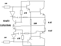
You can see the schetch of Q2 and Q4 here : http://home.online.no/~tsandstr/Otala amp 1973, original.htm
so they're triggering by current sensing. NB mosfets output.
so they're triggering by current sensing. NB mosfets output.
thank konrad! I remark that this circuit can not protect my amp perpectly . I have just buy a new pair of power transistor
Eva said:I would mute the amplifier internally first. Relays are not fast enough to prevent output devices from blowing, but as an example removing the bias to the input stage or shorting outpud device drive voltages/currets may be a fast enough solution
I have to agree with Eva. In the amp design I am working on now, the diff, VAS and drivers all are driven by a voltage regulation circuit that is switchable. Using some fast comparators and connecting them so that a +5V logic input will turn on both the + rail and the -rail at the same time, well...relative to a relay. 0V is off. The output collectors are not regulated and have + & - V all the time, but as the drivers are cut off, so are they.
This sort of shceme is good for using a logic circuit to control, and that opens the door wide open for all kinds of the protection circuits you can come up with. Sacrifice a few volts of power supply for control...I can live with that. Cheaper in the long run
- Status
- Not open for further replies.
- Home
- Amplifiers
- Solid State
- Power protection system