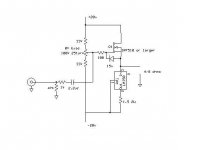
Here is an amp I threw together over the weekend. Very simple power follower with a lm350 used as a constant current source set between 1-2.5 amps depending on the mosfet used. DC coupling is adjusted by 100k pot. Pre amp required to get full output. Choke or chip regulated dual supply required. I use a choke regulated supply and ripple is below audible levels. Zener is to protect mosfet. I used IRF510 5A 100v and it sounds excelent, very clean with low distortion. Larger mosfets can be used but you cant beat the 510's 150pf input capacitance. I'm going to build a larger version with some 230's and p240's at higer voltages with a different regulator. I would be happy to hear any suggestions and someone please build one and tell me what you think, It doesnt take long. Schematic Included.

hi
I just read your post oct 2004 ?? but i build similar
project with good result.
www.loginnovation.com/jeapel
if you jump from irf 510 (150pf) to irfp240 1500 or 2000pf
you need a low zout driver
good side:
low distortion without feedback
good damping factor
bad side:
very neutral sound so a tube driver give some good harmonics
hoping you read this may 2005 ??
Re: schematic
I have tested this schematic with a 1,8 Amp currentsource using a LM323 volt regulator and a 2,7 ohm Dale 25 watt resistor.
It does cook a meal at 25 volt.
This was a lot better sounding than a IRF250 source with a current feedback with a BC546 Wilson transistor. That tended to be very harsh sounding). Even with a 1000 ohms gate stopper.
You need a lower bottom rail of course.
The problem I have with a pair of IRFP250/IRF250 running at 1 amp and 25 volt is that it sucks details so the level sort of is uneven - an unwanted physiological effect.
Mr. Steve said:schematic repost
I have tested this schematic with a 1,8 Amp currentsource using a LM323 volt regulator and a 2,7 ohm Dale 25 watt resistor.
It does cook a meal at 25 volt.
This was a lot better sounding than a IRF250 source with a current feedback with a BC546 Wilson transistor. That tended to be very harsh sounding). Even with a 1000 ohms gate stopper.
You need a lower bottom rail of course.
The problem I have with a pair of IRFP250/IRF250 running at 1 amp and 25 volt is that it sucks details so the level sort of is uneven - an unwanted physiological effect.
hi sajti very interesting design and if possible
i would like to see photo
-first your mosfet output:
1-your ccs bias ~3 amp is very similar to me but
without my small .01uF on gate my ccs is
unstable with high frequency
2-irfp 140 => cin=1700pf =>ron=.077ohm
irf540 => cin=1700pf =>ron=.077ohm
=> irf540 ~= irfp140
3-you are lucky to get big heatsink like that here
in quebec it s very difficult to get big heatsink
4-i like the auto bias with integretor tl072
-tube input:
1-ok long tail with ccs on cathode but which tube and
what ma. bias in each tube
2-why c3 and c4 return to Out and not ground
3-my infos is to drive mosfet with low zout tube to
integrate tube and mosfet together
-Pavel Macura follower said zout max.= 1000ohm
-http://www.zenn.com.sg/Why%20hybrid.htm
i am very intriging about your high frequency
and your high zout drive did you test with oscillo
bye 🙂
hi triode_al
"running at 1 amp and 25 volt is that it sucks details so the level sort of is uneven - an unwan"
I run 26 volt 1.55 amp with irfp140 ccs and the sound
is very good i dont understand your point maybe more
explications 🙂
"running at 1 amp and 25 volt is that it sucks details so the level sort of is uneven - an unwan"
I run 26 volt 1.55 amp with irfp140 ccs and the sound
is very good i dont understand your point maybe more
explications 🙂
jeapel said:hi triode_al
I run 26 volt 1.55 amp with irfp140 ccs and the sound
is very good i dont understand your point maybe more
explications 🙂
Jeapel,
The difference is the CCS which is (IMHO) probably better than an N/P pair - maybe I did something wrong, but there is an effect that the music is louder than one moght expect. As if the FET pair stores the signal and then
 --- jumps. I know this sound crazy.
  But on my scope I see no problems, a 4 ohm// 0,5 muF is completely solid rising edge; and the 8 ohm/4 ohm changes chows no drop in level.
 Even frequency goes to 200kHz +.
Still this singular effect of what I call 'physiological'.
So I have set aside this N/P pair with currently SJ135+SK50 one channel and IRF150/SK50 other channel aside.
My plans: I will restore my earlier CCS loaded IRF150 at 1,8 Amp. To see how that is again now.
I don't expect to understand the strange behaviour of the N/P pair.
 Could it be that one transitor blocks the other and blocks a movement of the voltage until some microseconds? Any idea someone? So here we have a secret of the SE style of Steve's and your design!?
triode_al strange
maybe ???
when bc546 is on the volt on gate drop very fast
when bc546 is off the volt on gate raise slowly
with 10k ohm
it s very unsymitrical ?? and maybe unstable too ??
take your irf250 and build a ccs like me
www.loginnovation.com/jeapel
also post a schematic would be a good idea
maybe ???
when bc546 is on the volt on gate drop very fast
when bc546 is off the volt on gate raise slowly
with 10k ohm
it s very unsymitrical ?? and maybe unstable too ??
take your irf250 and build a ccs like me
www.loginnovation.com/jeapel
also post a schematic would be a good idea
jeapel said:hi sajti very interesting design and if possible
i would like to see photo
-first your mosfet output:
1-your ccs bias ~3 amp is very similar to me but
without my small .01uF on gate my ccs is
unstable with high frequency
2-irfp 140 => cin=1700pf =>ron=.077ohm
irf540 => cin=1700pf =>ron=.077ohm
=> irf540 ~= irfp140
3-you are lucky to get big heatsink like that here
in quebec it s very difficult to get big heatsink
4-i like the auto bias with integretor tl072
-tube input:
1-ok long tail with ccs on cathode but which tube and
what ma. bias in each tube
2-why c3 and c4 return to Out and not ground
3-my infos is to drive mosfet with low zout tube to
integrate tube and mosfet together
-Pavel Macura follower said zout max.= 1000ohm
-http://www.zenn.com.sg/Why%20hybrid.htm
i am very intriging about your high frequency
and your high zout drive did you test with oscillo
bye 🙂
Hi,
I use forced cooling with some temperature controlled fans. It's running very slow in most of the time, so the noise is not too much.
I didn't found any oscillation with the ccs. I don't know why? All of my devices are mounted on the PCB, so the is no any wires.
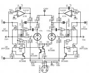
The two opamps act as DC servo circuit, and keep the output at 0 voltage, at any time.
Currently I working on upgrade, without DC servos, and single +20V power supply. Due the balanced mode, the offset is not critical, even with cold, or hot mosfets.
Currently I use IRF530s as output devices. All are made by SGS. They are pretty linear, and have low capacitances.
About the tubes:
You can use lot of different types, due the ccs. The bias will be constant with most of valves. The current of the ccs is about 8mA, so the bias is 4mA for each valves.
The C3 and C4 makes bootstrapping to increase the gain of the tubes. With this solution You can get up to 30, with E88CC I use now.
The whole amplifier has symmetrical feedback, with the gain of 3. It's enough with most of preamplifiers, and the feedback network was planned to give symmetrical output even with single ended driving.
I checked the output signal with scope, and it was OK. I think that IRF530 has low input capacitance, easily driven by 4mA bias. But if it not enough, I recommend to use ECC99 with up to 15-20mA. It can drive anything 😀
sajti
Hi
Referring to a schematic on post #3: Is it possible to operate it from a single 40 V supply, with the capacitor added on the output?
Thanks,
Vix
Referring to a schematic on post #3: Is it possible to operate it from a single 40 V supply, with the capacitor added on the output?
Thanks,
Vix
jeapel said:also post a schematic would be a good idea [/B]
I'll draw a schematic this weekend.
I used N channel where you use P channel in mosfet output current source around IRFP140. Interesting...
to sajti
maybe i overkill with 6as7 (2 x 13 watt) but
for me the ecc99 (2 x 5 watt) would be a good second
choice and now i understand why you get no drive
problem with e88cc it s your great feedback
30 to 3 (factor 10 or 20db) give a good
frequency extension (what is your -3db frequency)
with my 6as7 the feedback is factor 2 6db and all my internet
reading said factor 3 10db is the max because
high feedback give different sound
and same thing for the damping factor
irf530 670pf ron = .16ohm (but 2 x for you)
without feedback i need low ron high cin and low zout driver
bye it was a good discussion 🙂
jeapel said:to sajti
maybe i overkill with 6as7 (2 x 13 watt) but
for me the ecc99 (2 x 5 watt) would be a good second
choice and now i understand why you get no drive
problem with e88cc it s your great feedback
30 to 3 (factor 10 or 20db) give a good
frequency extension (what is your -3db frequency)
with my 6as7 the feedback is factor 2 6db and all my internet
reading said factor 3 10db is the max because
high feedback give different sound
and same thing for the damping factor
irf530 670pf ron = .16ohm (but 2 x for you)
without feedback i need low ron high cin and low zout driver
bye it was a good discussion 🙂
Yes, the feedback is about 20dB, but it's not too much, with two stage amplifier. It's very stable. I never had any oscillation, or other, even with capacitive load.
High feedback can results different sound, but mainly with more stages. I used this amplifier with E82CC, which gives the gain of 17. With it the feedback is 5, which is not too much.
When You use the mosfet as source follower the input capacitance is not important. The reverse (Miller) capacitance is more interesting. But this value is about 29pF with SGS IRF530.
Another issue I don't agrre, is the Rds ON. Which is important only in switching mode. In linear mode the gm is more important, and it will gives the output impedance for Your amplifier.
So don't care with the Rds ON. This is absolutely not important factor in linear application.
sajti
Yes, the feedback is about 20dB, but it's not too much, with two stage amplifier. It's very stable. I never had any oscillation, or other, even with capacitive load.
.......internet guru 🙂 are not speaking high feedback with
oscillation but harmonics composition sound feeling
sound impression
high feedback can results different sound, but mainly with more stages. I used this amplifier with E82CC, which gives the gain of 17. With it the feedback is 5, which is not too much.
When You use the mosfet as source follower the input capacitance is not important. The reverse (Miller) capacitance is more interesting. But this value is about 29pF with SGS IRF530.
........cin total=cin+c miller the 670pf is always there no !
cin=29pf ?? are you sure
Another issue I don't agrre, is the Rds ON. Which is important only in switching mode. In linear mode the gm is more important, and it will gives the output impedance for Your amplifier.
So don't care with the Rds ON. This is absolutely not important factor in linear application.
..........if zout=1 and speaker 8 damping factor =8 , have you
a math example with ron and gm for the zout
without feedback thanks 🙂
I think, that this is question of the taste. The switching mosfets has not so linear charactersitic with low current. The feedback helps to linearize it. It helps to reduce the output impedance. I use 12-20dB of feedback in my amplifiers.
Cin (C gate-source) is not so important if the mosfet works as source follower, because the AC voltage on the gate, and on the source is almost same. (Gain=1). This means that the charge of this cap doesn't change, so no current flow. If You use the mosfet as common source stage (as in the Zen amp) than Cin is important.
The Cgd (gate drain) is 29pF. This is the important in source follower application.
Yes I have example for output impedance:
Zout= 1/gm
Without feedback.
sajti
I think, that this is question of the taste. The switching mosfets has not so linear charactersitic with low current. The feedback helps to linearize it. It helps to reduce the output impedance. I use 12-20dB of feedback in my amplifiers.
.........ok yes mosfet more bias more linear but more heat
your opinion 1 2 or 3amp (my bias is 1.55 amp)
Cin (C gate-source) is not so important if the mosfet works as source follower, because the AC voltage on the gate, and on the source is almost same. (Gain=1). This means that the charge of this cap doesn't change, so no current flow.
..........??????? ok for steady mode but :
-if V source = 10 V and V gate =10 V
-now V gate jump to 15 V now there is
transient mode with zout (driver) and 670pf
If You use the mosfet as common source stage (as in the Zen amp) than Cin is important.
..........yes Zen is terrible for that
The Cgd (gate drain) is 29pF. This is the important in source follower application.
Yes I have example for output impedance:
Zout= 1/gm
...........thanks it s easy my irfp140 gm=9.8
zout=.1 ohm DF=80 but in pratical there is
my cout and the crossover network inside speaker
maybe a good project would be a high damping amp
no cout and just one speaker (wide band) no crossover
just to see the sound
Without feedback.
- Status
- Not open for further replies.
- Home
- Amplifiers
- Solid State
- Power follower class A Mosfet DC coupled.