Amplifier Modules:
AE140-M Power Audio Amplifier Module 140W with QFET®MOSFET transistors
AE200-M Power Audio Amplifier Module 200W with QFET®MOSFET transistors
AE400-M Power Audio Amplifier Module 400W with QFET®MOSFET transistors
AE2614 14W HI-FI Amplifier module with TDA2614
AE7294 Power Audio Amplifier Module 100W with TDA7294
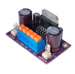
LPS-1 Linear power supply module 0-50Vdc/15A - 2x12.000μF/50Vdc
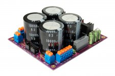
LPS-2 Linear power supply module 0-63Vdc/20A - 4x10.000μF/63Vdc
Visit my eBay page for Power Amplifier Modules:<click here>
AE140-M Power Audio Amplifier Module 140W with QFET®MOSFET transistors
AE200-M Power Audio Amplifier Module 200W with QFET®MOSFET transistors
AE400-M Power Audio Amplifier Module 400W with QFET®MOSFET transistors
AE2614 14W HI-FI Amplifier module with TDA2614
AE7294 Power Audio Amplifier Module 100W with TDA7294
LPS-1 Linear power supply module 0-50Vdc/15A - 2x12.000μF/50Vdc
LPS-2 Linear power supply module 0-63Vdc/20A - 4x10.000μF/63Vdc
Visit my eBay page for Power Amplifier Modules:<click here>
Attachments
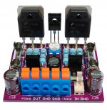
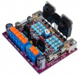
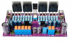
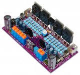
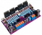
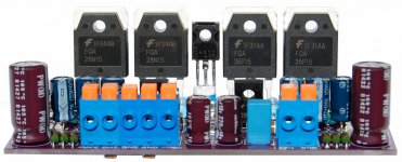
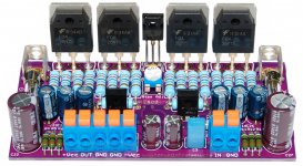
400W AUDIO AMPLIFIER MODULE
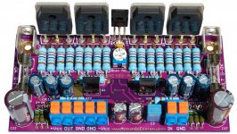
AE400-M is a class AB power audio amplifier module, with discrete components and QFET®MOSFET final power stage transistors produced by Fairchild company.
A symmetrical stage resolves the problem of the amplifier saturation and greatly reduce distortion at high output power.
For a very high stability of the amplifier, both for the input stage, the double differential voltage amplifier (VAS) and for the final stage, were selected transistors with identical characteristics. The transistors from the input stage are areas of Dual Matched transistors (identical characteristics).
In the output stage were used QFET®MOSFET transistors with the same ON state resistance (RDS-on) for the channel N and channel P transistors.
In order to obtain a high response speed the "Pilot" transistors from VAS were elected with very low capacitance Cob-2,6 pF.
In order to obtain a very high output power and an output current of over 40A, in the routing process / design of PCB were duplicated all power routes, for the bottom and the top layer.
Technical Data
Operating voltage range very extended
High capability of the output current 40A - QFET®MOSFET Power Stage
Extended load 4-16Ω
High output power max. 400W RMS Power
LEDs „Power Monitor/Status Monitor” Blue-Power ON, Green-OK, Red-Fault.
No power on noise
Very low distortions
Very low noise
Short-circuit protection (current limitation)
Quick connect type power connectors
Small Module 100x50 mm
High temperature PCB FR4 with metalized holes and finishing with a gold layer
Brand Name components on the highest quality
Set of mechanical fixing accessories, Pad for electrical insulation and envelope with silicone paste
Electrical Characteristics
Output power RMS - THD 0.025%
Vcc = ±60V, 200W/8Ω / Vcc = ±55V, 300W/4Ω
Output power RMS - THD 0.06%
Vcc = ±70V, 250W/8Ω / Vcc = ±65V, 400W/4Ω
Idling current: 30-60 mA
Input impedance: 33K
Frequency Response: 5Hz-40KHz (-3dB)
Response speed (Slew Rate): 70V/us
Total harmonic distorsions (THD): 0.0042%(5W-1KHz) / 0.0075%(50W-10Hz-25KHz)
The manual of the module and other characteristics you can find here
Attachments


- Status
- Not open for further replies.