Hello Everyone,
I am trying to modify a project my father was working earlier, the question I am having now is on local power rail bypass.
I know there has been a lot of discussion on bypass and I know bypassing at the cap bank is no no, but a good practice to have local bypass if the main cap bank is some distances (maybe inches) away.
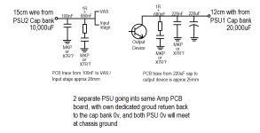
I will be doing 2 PSU for each amp board, one to drive the output stage with a bigger PSU, and one smaller PSU to drive the input and VAS. Both PSUs are approx 12~15cm away from their respective power entry points on the amp board. Each power rail is 35VDC, from 25v transformer secondaries.
The bypass method I am using is have in mind is really a copy from an article from TNT Audio by Dejan Veselinovic. What I think is good is the RC right before the device.
Main questions I have are:
1. Should I also have the 220uF bulk filter cap for the PSU2 (driving Input stage and VAS)? Currently I have no plans to but I can still add in if that is a good thing.
2. Which is preferred (X7R SMD type or MKP box THT type) for the 100/220nF bypass as well as the 680nF RC filter? Their cost difference is really very small for DIY, and while X7R is smaller in footprint, I am doing double layer board so space is not really an issue.
Hope to get some feedback soon as I'll be having a one-week break soon, and will be a good time to make some progress.
I am trying to modify a project my father was working earlier, the question I am having now is on local power rail bypass.
I know there has been a lot of discussion on bypass and I know bypassing at the cap bank is no no, but a good practice to have local bypass if the main cap bank is some distances (maybe inches) away.
I will be doing 2 PSU for each amp board, one to drive the output stage with a bigger PSU, and one smaller PSU to drive the input and VAS. Both PSUs are approx 12~15cm away from their respective power entry points on the amp board. Each power rail is 35VDC, from 25v transformer secondaries.
The bypass method I am using is have in mind is really a copy from an article from TNT Audio by Dejan Veselinovic. What I think is good is the RC right before the device.
Main questions I have are:
1. Should I also have the 220uF bulk filter cap for the PSU2 (driving Input stage and VAS)? Currently I have no plans to but I can still add in if that is a good thing.
2. Which is preferred (X7R SMD type or MKP box THT type) for the 100/220nF bypass as well as the 680nF RC filter? Their cost difference is really very small for DIY, and while X7R is smaller in footprint, I am doing double layer board so space is not really an issue.
Hope to get some feedback soon as I'll be having a one-week break soon, and will be a good time to make some progress.
Attachments
I forgotten to mention, that this will be an approx 60W AB amp.
The speaker return, all signal ground and HBR, will all meet at the PSU1 ground point on the PCB, then a thick wire back to the PSU1 cap bank 0v T bar, where the cap bank 0v is "separated" from the wire from amp board, with the wire going to the chassis ground (the Bonsai-method 🙂 ).
Cap bank 0v <-> wire to chassis ground <-> wire from amp board
You can isolate the VAS and input stages from the output stages using a 5-15 Ohm resistor and an electrolytic cap after this (say 100uF to 220uF) to the star ground point on your PCB. The electrolytic should be bypassed by suitable small-value ceramics. I have not found it necessary to use damping resistors in series with the low-value bypass caps in power amplifiers. In small signal high-speed applications like a DAC or ADC, this type of decoupling is important, as it is when using certain IC regulators (see the data sheet for the reg you are using - the manufacturer will always provide the correct application guidance).
For a power amp, I use the VAS/front end filter described above, and I do the HF decoupling with 1uF X7R 0805 capacitors - usually 1 to 2 after the 15 ohn resistor. On the output stage side, use local electrolytic decoupling of 100 to 1000uF with 1-2 pieces 1uF X7R decoupling.
What is very important here is to make sure the loop areas between the power supply rails and the ground returns are as small as possible. The best way to do this is to lay the rail tracks on top of the 0V return tracks. For class AB amplifiers, also lay the central output bus track next to or better still over the rail tracks. This will reduce radiating loops and thus noise and distortion. When you lay your PCB out, start with the output stage and the tracks I mentioned above first.
For the feedback resistor, lay this over a separate ground track that must run from the PCB star ground to the front end. No decoupling capacitor returns must connect to this low-noise ground track - only the front-end biasing and feedback return. Again, keep all loops as small and tight as possible.
🙂
Thank you Bonsai.
Thanks for the note on isolating the power rails for different stages.
Good to know that X7R is suitable in power amp HF filtering, I was not very sure as most of the discussion on using X7R are on HF Opamp applications.
On the ground loop, yes of course, I'd spent quite a bit of time going through the information on your site 🙂
Thanks again