Hi,geminni said:I have made 4 quasis dc protections. Two of them had to do the job 🙂 Two channels, from four, gone bad and put some dc on speaker out. Both speaker were saved!! 🙂 The transformer is 2x39v which gives some 2x55dc. One channel had +35 volts on speaker output and other had full 55 volts! The relays were nothing special, not some high-end sort of. The thing is that protection worked and i'm very pleased.
Doing some test with it i can see that when dc i smaller then it takes much more time for relay to disconect. For 12 volts i takes second or so, for smaller then 12 it takes more seconds. Will that 12 volts within one second burn speaker?
what is the filter on the input to the DC detect?
I think bigger speakers will survive 12V for 1second, that's 18W into a stationary 8r0 voice coil. But, 48W into a stationary 3r0 VC.
I tested another DC detect circuit and found that a 9V battery gave almost instant cutoff using a 0.8Hz filter, 200mS time constant.
I wish I knew how to measure the cutoff time for different offset voltages.
Any thoughts on a simple time measuring system?
A Spice simulation will give you the answer.
Where is the circuit ?
Most circuits I have seen require at least 0.6 volts to trigger. Nothing happens less than that . At higher voltages the time taken to trip decreases depending on the input RC time constant.
Where is the circuit ?
Most circuits I have seen require at least 0.6 volts to trigger. Nothing happens less than that . At higher voltages the time taken to trip decreases depending on the input RC time constant.
Hi Ashok,
could I ask a big favour?
Could you post a sim with the various input and output statements that would let me investigate the time vs voltage characteristic?
could I ask a big favour?
Could you post a sim with the various input and output statements that would let me investigate the time vs voltage characteristic?
I use Beige Bag's Spice program and so I do not write out any statements.
I draw the schematic and run the required simulation.
Give me a circuit and I can simulate it for you.
🙂
I draw the schematic and run the required simulation.
Give me a circuit and I can simulate it for you.
🙂
Hi,"The quick brown fox jumps over the lazy dog."
can it be done in less than 35?
The circuit as posted has a few problems, but, let's see the sim and we can examine in detail.
Thanks paid in advance to Ashok.
edit,
could you add a resistor from the collector of Q5 to the base of Q4? Set it to 10M initially.
And another resistor in the emitter feed to Q5. Set it to 0r1 initially.
Finally, a capacitor from Q5 collector to ground. Set it to 1nF initially.
too late for an edit.
cap should have been located at Q5 emitter to ground.Finally, a capacitor from Q5 collector to ground. Set it to 1nF initially
The negative offset also switches almost as fast.
Circuit 2 had to be modified as plus and minus offset see different loads ( base current or emitter current ). So the relay driver now is a darlington to reduce the drive current required for switching.
Q1 , Q2 .... BC546B or BC547B
Q3 ............ BC556B or BC557B
Q4 ............ BC327
Circuit 2 had to be modified as plus and minus offset see different loads ( base current or emitter current ). So the relay driver now is a darlington to reduce the drive current required for switching.
Q1 , Q2 .... BC546B or BC547B
Q3 ............ BC556B or BC557B
Q4 ............ BC327
Attachments

The circuit in Ckt-2 needs some modification to handle 200 watt 20 Hz signals without tripping.
The values shown will not trip with 20 Hz 70 volt peak ac. But with a 1 volt dc offset ( + or - ) on the 70 volts ac will trip the relay.
However the switching time with low voltages will now be much larger though quite acceptable.
+1 volt dc offset about 2.4 sec
-1 volt about 6 sec
+1.5 volt about 1.5 sec
-1.5 volt about 2.7 sec
Attachments

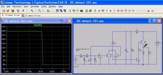
ashok said:OK here is the response. I redrew the circuit ( ckt-1 ) but it is exactly the same as the one posted earlier.
The switching time is nearly 4 seconds and it is also very slow.
I modified the circuit in ckt-2 . It switches very fast in about 0.4 sec.
HI Ashok,
what was the offset voltage you used in this sim? (post #1788)
Cheers
Q
Hi Quasi,
I used +1 volt and also checked -1 volt dc offset.
Note that by using positive feedback it's possible to speed up the switching. That's what Andrew was suggesting in his post just before mine.
AndrewT:
The 10 Meg +ve feedback speeds up the switching very well. The resistor on the base emitter of Q5 sharpens up the 0 to 5 V rise time . Without that resistor it is a slow curve till about 5 volts.
Why the 1nF across the supply line ( Q5 emitter to ground )?
Cheers,
Ashok.
The circuit I posted cannot be relied on for DC offsets below 2.5 volts. While this may not suit everyone it is highly likely that a fault condition will result in a DC offset of much more than this.
At 2.5 volts the relay will drop out in about 1,500 mS and this goes down to 235 mS for a DC offset of 20 volts (a far more likely condition). Below are the times for various DC offset voltages plus a graphic of simulation for a DC offset of 5 volts.
Cheers
Q
DC offsett Time (ms)
2.5v - 1,540
3v - 1,100
3.5v - 920
4v - 800
4.5v - 710
5v - 635
7.5v - 455
10v - 365
15v - 280
20v - 235
Attachments
Apologies to all. In my simulation of the original dc-protect circuit I was looking at the wrong signal !
I was actually seeing the relay turning on after a few seconds after power up. Simple nifty arrangement.😉
In my modified circuit the relay turns ON when there is a fault. So it cannot be used as the relay for the speaker.
I modified the circuit to turn OFF when there is a fault.
However at the moment it doesn't have a turn on delay like the original circuit.
Quasi you are right. The original circuit will not switch at 1 volt.
The modified circuit seems to switch at +1 V and at -1.5 V. Below that it's unreliable. But as you pointed out dc offset on failure is usually a much higher voltage.
Attachments

Hi,
the emitter resistor and the capacitor at the output will allow snap actuation of the relay at power up. The cap charges up through the resistor to the open circuit voltage of the supply (about 24V).
The transistor switches on and the 24V stored on the cap fires a 12V relay VERY quickly. The cap discharges and the resistor feeds just 7 or 8V (or even less) to the relay to hold it in gently and keep the relay coil cool. Cutting the transistor now allows the relay to release more quickly than if it were supplied with it's rated voltage.
The relay delay on opening and closing can be into tens of mS. This voltage manipulation can reduce these delays significantly.
1nF and 0r1 should take these mods out of significance. Changing them to 22uF and 1k should give the snap action. But exact values will depend on the coil resistance of the chosen relay, a bit of experimentation will be needed.
In that last post, is R7 mimicing the relay coil?
Re: Nmos200 TO247 version.
What is the correct schematics (value of transistors and components) for this version?
quasi said:.
A pair of 250 or even 300 watt TO247 could be interesting.
nmos200-to247 layout & tracks.pdf
Cheers
Q
What is the correct schematics (value of transistors and components) for this version?
Re: Re: Nmos200 TO247 version.
No change to the Nmos200 schematic is needed. Using these FETs means you can run slightly higher rails (55-60 volts) and get a bit more power. If power is what you're after though, you are better off building the Nmos350 or 500.
Cheers
Q
grechejr said:What is the correct schematics (value of transistors and components) for this version?
No change to the Nmos200 schematic is needed. Using these FETs means you can run slightly higher rails (55-60 volts) and get a bit more power. If power is what you're after though, you are better off building the Nmos350 or 500.
Cheers
Q
Hi Andrew,
I hadn't figured out the position of the R and C correctly. As you say the RC will speed up switching on and off of the relay and also keep it cooler while it's on. Great idea.
Yes R7 was mimicing the relay coil.
Cheers,
Ashok.
I hadn't figured out the position of the R and C correctly. As you say the RC will speed up switching on and off of the relay and also keep it cooler while it's on. Great idea.
Yes R7 was mimicing the relay coil.
Cheers,
Ashok.
About original DC protection, can it be modified to work with 12 volts?
I have a bunch of 12v relays and 10-12 volts transformers.
I tried to make some voltage drop form 55 volts but it doesn't work to me. I tried zener with transistors, made calculation but it only heats up the transistor very much. I don't want that much heat eaters in amplifier box. I feel much more safe with separate transformer 😀
I have a bunch of 12v relays and 10-12 volts transformers.
I tried to make some voltage drop form 55 volts but it doesn't work to me.
I tried zener with transistors, made calculation but it only heats up the transistor very much. I don't want that much heat eaters in amplifier box. I feel much more safe with separate transformer 😀- Home
- Amplifiers
- Solid State
- Power amp under development