Agreed that if you do have enough current drive in the VAS, or if each VFET is in a dedicated sub-circuit, like in the Stochino amp, they can be made to sound great. In fact, when done right, VFET output stages do not exhibit the 'etched' sound of Bipolars nor the 'haze' of Lateral FETs.
.... or if each VFET is in a dedicated sub-circuit, like in the Stochino amp, they can be made to sound great. In fact, when done right, VFET output stages do not exhibit the 'etched' sound of Bipolars nor the 'haze' of Lateral FETs.
Exactly, but it's the sub-circuit that makes the difference. Essentially, the Vfet and the sub-circuit act as one transistor, at least as the amplifier sees it. If the sub-circuit can make both Vfets appear as a more 'ideal' transistor to the VAS, then it present an opportunity to be able to use less current in the VAS. I am a fan of small VAS currents, leaving open lots of small signal devices to choose from😉, and utilizing the high GBW of the follower stage(s). If it only takes a few uA to drive the sub-circuit, then the VAS can be small signal. Since these transistors are so fast, the phase shift is small and the trade-off is minimal. Also, who says there has to be a global loop?🙄
CBS240, I remember seeing some of your hand-drawn schematics of amps designed by you; designs on similar lines. Maybe, if it is not a commercial conflict, you can present of couple of ideas.
Elektor also used 'super transistors' using bipolars in the same way, comprising of one and two small signal, one medium power and one npn output device to make up both a pnp and npn super transistor. The current gain is very high within this loop and the voltage gain is unity. Thermal tracking consists of tying together the VAS small signal transistor and the small signal transistor of the super transistor.
They had such a 40/60 watt amp designed on the lines of the Crescendo and mini-crescendo - sounded very good for that time (around 1984 I think).
Like to see more implementations and ideas with Mosfet output devices. Thanks.
Hi
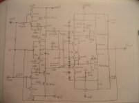
Well, since the issue is whether or not to use vfets for linear audio, I will show how I used them in the above pictured circuit. Basically it is Bob's EC mosfet output stage. I added a few things, cascodes, a few different components, but the principle is the same.
+/-10V is required from the VAS plus the signal swing, but only a few uA of current is needed so a small signal current driven cascode, transimpedance VAS can be used.😉😉
C6026/A2154 has nice linear gain but in SOT-923, are quite small, Pd=50mW. Simple and improving solution, cascode with J-fet.🙂
It is important for the error correction stage to have as large of BW as possible. C2755 or C2223 and H81 are very fast devices. The EC amp transistors are placed under the drain pin of each respecting output fet. In the photo you can see the drain pin is longer, and underneath is the small SOT-23 error amp to compensate thermal drift.🙂 The photo diode is a IL300 linear optocoupler and is used to set bias. There are two of these output stages that are bridged and I wanted to be able to set bias of both with one pot but keep them electrically isolated. So the diode simply replaces the pot as in Bob's circuit. I added totem pole drivers, and a clamp to help give clean clipping and prevent overcharge of the gates and crossconduction.(all charge used to turn on the fet has to be removed in order for it to turn off) Since the drivers require 30-40mA of current which usually would be sourced by the higher voltage PS; a larger, voltage regulator would be required and there would be excess heat generated by the drivers. Instead I used bootstrapping to provide this current from the power rails and thus the circuit needs less than 3mA from the +/-35V supply.😀
The drivers are KSC2690/KSA1220 and are mounted to the small heatsinks. On the sides of these heatsinks are the source resistors, 50 mOhm TO-126 power metal film resistors from Caddock. All other resistor values written like SMD notation, 100=10 Ohms, 101=100 Ohms, 102=1K, 103=10K, ect. Transistors 1/2 & 2/2 is a B2227A Super SOT-6.
Attachments
Last edited:
- Status
- Not open for further replies.