Hi all.
I'm a newbie to this forum.
I'm working on a very old Crown power amp and am looking for a good reference book that has waveform analysis. ie:if I feed a 1k sine wave into it and get something else on the scope, the book can lead me in the right direction as to what the new waveform means. I have a dual trace scope.
I'm in the Toronto gta.
Thanks
Cracklin
DC-300?
D-150?
D-60?
Get the schematic.
All power amps tend to follow a similar receipe:
gain stage in the front end/phase inverter, something to drive the outputs, something to spread the voltage apart from the drivers for the upper and lower rails, and then usually a current gain output stage in the form of a follower.
Since these amps have big feedback, you'll get garbage out or nothing much out if any of the devices are toast.
What one usually wants to do is to look for obvious failures like burnt resistors, and shorted transistors.
You may want to look for the magic ~0.6vdc base to emitter drop on the transistors - if it's not there, then there is a problem.
Excess current is also a clue...
Often one actually has to remove the transistors and test them.
The early Crowns used an IC in the front end, that can die too.
There is no book that I know of that explains amplifier troubleshooting very well, or if there was one, one that you could just read and follow along without some real knowledge of how circuits work.
Sorry for the bad news...
Otoh, folks here can answer questions about how the circuit works...
_-_-bear
PS. if you need a very good book on electronics, The Art Of Electronics by Horowitz and Hill is excellent and unusually well written... it's actually readable! 😉
Thanks for the quick reply.
It's a D150.
By the way, the OD leds for both channels go on when I turn it on and whether I have a signal going in or not.
The gain works as well when I turn it up or down.
Also, if I can manage to get a jpeg of the output from the scope,
would you be able to get some idea of what's going on?
Cracklin
Crown have service manuals on their website with full test procedures. This would be a good place to start.
Check all of the transistors/diodes for shorts. Check the power supply caps for equal DC voltage and ripple.
Thanks,
I know about the manual. I've downloaded it.
As I mentioned before, I need a reference to help me analyze the output waveform when a 1k sine wave is fed into the amp. ie:
what does oscillation look like on a scope?
I know about the manual. I've downloaded it.
As I mentioned before, I need a reference to help me analyze the output waveform when a 1k sine wave is fed into the amp. ie:
what does oscillation look like on a scope?
If there is a known problem or goal, it would sure help if you stated what it is. You have not given much information. And it's much more difficult and time-consuming for anyone to give you advice in generalities. So please try to state the known problems, or your goals, and present the results of whatever tests or measurements you've performed. Then be prepared to perform suggested testing and report back. There are many people here who would like to try to help you. But you have to help them help you, as much as possible, by providing all information that might be relevant.
OK.
Rather than starting by looking at the amplifier output, I suggest you start with the power supply rail voltages. If those are not within the published specs, it doesn't make sense to look at much else. (And if one of them is low, for example, you'd first have to try to determine if a power supply fault is responsible for not keeping it up, or if, instead, something downstream is dragging it down.)
If the unit is very old, the first likely suspects are probably all electrolytic capacitors. If you don't have an ESR meter, maybe you can use this: http://www.fullnet.com/~tomg/esrscope.htm . (If you don't have a suitable square wave or pulse generator, you should be able to slap one together with a couple of op amps, or an NE555 IC, for a couple of dollars or so. Schematics are on the web.)
Other good possibilities for causes of problems in old equipment include dirty or worn-out potentiometer elements and switch contacts, as well as connectors and sockets. Get some Caig De-Oxit (see Caig.com), probably in both the spray-can form and the concentrate's needle-applicator form.
Before even using any test equipment, do a thorough visual inspection, looking for any discolorations of components, wires, PCBs, case interior, etc, and for leaking or bulging electrolytics, or evidence of past electrolyte leakage, and anything else that looks slightly odd, plus evidence of past repair attempts, damage, spills, mice, etc. A magnifying glass and a bright lamp should be helpful.
If you have the service manual, as you said, and it has a recommended troubleshooting procedure, or a calibration/alignment procedure, follow that first. If there are test-points' voltages or waveforms, check them against your unit, using the specified controls settings and operating conditions.
Regarding your question about what oscillation looks like on an oscilloscope: It depends. If the oscillation is at a very-much higher frequency than your scope's bandwidth, which you failed to mention, and has a relatively low amplitude, then you might not see it at all. If the oscillation is 'big-enough', but is beyond your scope's bandwidth or its trigger bandwidth, it might just look like a 'fuzzy trace'; anything from small to very large, depending on the oscillation and your scope, settings, etc etc. But if your scope IS capabable of a fast-enough sweep speed, and can trigger on it, a high-frequency oscillation will probably just look like some periodic waveform. If something is coming out that is at a much higher frequency than you're putting in, it's probably 'not a good thing', and could also damage or destroy components in the amp.
Later on, after the amp is working pretty well, you can also bang some square waves into the amp's input, and see what sort of ringing you get, on the leading edges of the output. That might tell you something about the frequencies at which it would 'like' to oscillate, and might even point you toward some compensation loop that needs trimming, or something.
Point taken.
My scope is a Tektronix 10mhz storage oscilloscope.
I have a sign wave gen. I don't have a square wave gen. but will get one or make one soon. One problem that is describable is that the OD leds go on when the amp is turned on(i/p signal or not). It probably is something in the power supply. I've tested the power caps. They are fine. I've cleaned the pots with a quality spray. I've also swapped the op amp. The amp is very old and the paper caps probably need replacing anyway.
Thanks for your extensive reply.
I won't post anything further till I undertake your suggestions.
I've attached a jpeg of the scope reading.
cracklin audio
Attachments
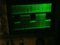
The top waveform is from the gen. 1k tone.
The bottom is taken from the output of the amp( spkr lugs).
The bottom is taken from the output of the amp( spkr lugs).
cracklin audio said:Point taken.
My scope is a Tektronix 10mhz storage oscilloscope.
I have a sign wave gen. I don't have a square wave gen. but will get one or make one soon. One problem that is describable is that the OD leds go on when the amp is turned on(i/p signal or not). It probably is something in the power supply. I've tested the power caps. They are fine. I've cleaned the pots with a quality spray. I've also swapped the op amp. The amp is very old and the paper caps probably need replacing anyway.
Thanks for your extensive reply.
I won't post anything further till I undertake your suggestions.
I've attached a jpeg of the scope reading.
cracklin audio
Very good.
You're still a little short on details. But you'll get there.
What is the Tek model designation? Is it one of the T900-series? What probes do you have?
Please define "OD". (It's a good idea to always define each acronym or abbreviation, the first time it's used at least.)
How did you test the power supply's smoothing caps, exactly?
Which spray did you use to clean the pots? Or, what are its main ingredients? Do you know what kind of pots they are?
Was there anything else connected to the speaker terminals, when that scope display was taken? If there is a volume or attenuator control on the amp, what was its setting? And, mainly, what were the scope's vertical attenuator settings? Do you know what the amp's maximum input voltage peak should be?
That is an interesting scope display. It should make it easier to track down the problem.
IF none of the power supply rails are doing the same sort of thing (in a significant way, at least), you could probably just start from the input and scope your way in, looking for the point where the signal starts cycling, like the output is, which might pretty-quickly narrow it down to at least the area where the problem is (well, maybe at least where it ISN'T).
If the power supply is the main problem, it shouldn't be too difficult to diagnose and solve.
I don't have your amp's schematics, and am not familiar with it. Does it have a plain linear supply, i.e. with transformer, rectifier bridge(s), filter caps, and possibly regulators? Or is it a switchmode type?
I can only answer some of your questions 'cause I'm at
work.
The OD is overload leds.
I tested them on a proper capacitor tester(ESR).
The spray is MG chemicals "NU-trol control cleaner with
special lubrication oils". There are pots on the input for left and right.
I had a dummy load with heat sinks attached(by the way,
they were getting pretty hot).
The power supply has the transformer going to a bridge
rectifier with filter caps.
I'll send the rest(if I know it) later.
No need to reply till then
And thanks again
P.S. When I said I was a newbie I was referring to this forum
as well as power amp electronics.
I appreciate your patience!
cracklin audio said:Thanks,
I know about the manual. I've downloaded it.
As I mentioned before, I need a reference to help me analyze the output waveform when a 1k sine wave is fed into the amp. ie:
what does oscillation look like on a scope?
oscillation looks like the trace is thicker than normal or "fuzzy". sometimes you may see a signal that looks like it has hair. that's oscillation. some amps seem to be stable until they clip, some will oscillate only on the positive or negative half. some will oscillate for the whole waveform. make sure you have as little capacitance as possible on the test load, as this can cause oscillation when there really is no problem other than a shortcoming of the design. crowns should be fairly stable, since one of the design considerations in pro-audio is long speaker cables.
Hi cracklin,
You are in good hands with these guys here. There is also one more guy that I know works/worked on these, Chris (Anatech) ia another good reference.
He is in Canada but I think Ontario.
Maybe he will drop in! Or you could prod him if it gets necessary.
Good luck!
Regards//Keith
You are in good hands with these guys here. There is also one more guy that I know works/worked on these, Chris (Anatech) ia another good reference.
He is in Canada but I think Ontario.
Maybe he will drop in! Or you could prod him if it gets necessary.
Good luck!
Regards//Keith
Gootee.
The pots are 25k log, attenuators.
The scope is a T912. The lead is a Tektronic. I'm not sure what the value is.
Cracklin Audio
The pots are 25k log, attenuators.
The scope is a T912. The lead is a Tektronic. I'm not sure what the value is.
Cracklin Audio
Hi Cracklin Audio,
Thank you.
So, do we have a plan, yet, for the next step in trying to diagnose your amplifier's problems? Or have you already started?
By the way, do you have a multimeter, or a Volt-Ohm meter, or something like that?
One thing I should emphasize, since you said you're new to power amp electronics: Be safe!! If the cover is open and the unit is plugged in, even if it's not turned on, you can be killed pretty easily if you aren't cautious. And even if it's powered off, the capacitors might still be potentially lethal.
Take off watches, rings, necklaces, etc. Always keep one hand in your pocket when working in 'live' AC-mains-powered equipment. And it's best if someone else is nearby.
Another reason for caution is that it's pretty easy to cause more damage, if your probe slips while you're poking around in a powered-up amplifier. I *HATE* when that happens! ;-)
If necessary, or maybe even just if possible, assemble your measurement setup and connections with the power off, then power on and take readings, then power off before changing connections or unhooking everything.
Having some short "clip leads", i.e. with clips on both ends, can be very helpful. It's usually easy to find (or make) the kind with small alligator clips on each end. And there are also some with much-smaller spring-loaded 'retractable-wire-hook' types of tips, kind of like some scope probes have, that are nice.
Also, to protect your scope, and you, it's probably best to assume, for the foreseeable future, that your scope probes' ground leads should ONLY be connected to "ground" points, in your amplifier. [If for some reason you MUST try to get a scope display of a voltage between two non-ground points, you can use two probes, differentially, i.e. display one channel minus the other (although now I forget if the T912 even has that function; I think so).]
OK.
Have you found anything in the downloaded manual that looks like it might be helpful?
(If you have the URL for that download, I'd like to try to download it, too.)
BY the way: If you don't know enough to even ask more questions, yet, and don't know where to start, that's OK. You can just try to familiarize yourself with the interior of the unit, and the manual. And someone here will probably come up with some suggestions, soon enough.
Hey Gootee.
http://www.crownaudio.com/gen_htm/legacy/legacamp.htm
This link will get you to the schematic for the D150a. It's in part 2.
Thanks for the electricution warning. I do have a great respect for electricity.
One thing about the bridge rectifier. From what I understand,
if you feed a full wave into a bridge, you should get a full half wave out and then the big caps smooth it out so you get DC, ie: figure 2 in this link
http://hyperphysics.phy-astr.gsu.edu/Hbase/electronic/rectbr.html
On the actual bridge rectifier, there are four terminals,two for the AC from the transformer(not marked) and two for the rectified output(marked plus and minus..... - and +). I'm getting a sine wave at the output. Is this possible? Or could I be using wrong test points?
Looking at the scope photo, it indicates that the positive half cycle is being clipped by a protection circuit that fires for a few cycles and then turns off and back on. The output waveform is clipped on both half cycles. The signal generator is overdriving the input. I'm guessing that the generator frequency is above 10khz.
As I recall the Crowns had a bootstrap circuit. There was a cap that used to fail. That could explain the positive half cycle problems.
As I recall the Crowns had a bootstrap circuit. There was a cap that used to fail. That could explain the positive half cycle problems.
- Status
- Not open for further replies.
- Home
- Amplifiers
- Solid State
- power amp repair