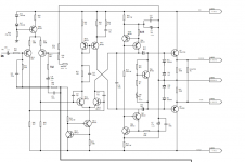
I have a power amp front end with Peak detection and DC, HF, and over temp protection that I plan to use in a project (another one) and need some help.
My first 2 question are:
Can I test this FE without the power stage ?
Can I lower the power supply for it ? (original power supply was 160Vdc (80/0/80))
Any suggestion(s) is/are welcome
Sorry for the low res of the schematic
My first 2 question are:
Can I test this FE without the power stage ?
Can I lower the power supply for it ? (original power supply was 160Vdc (80/0/80))
Any suggestion(s) is/are welcome
Sorry for the low res of the schematic
Attachments

Thanks again rayma I do see the node with R15/17 but what is confusing me ( it has been a very long day) is that without the output mosfets I have nothing to connect to it (I must be missing something...)
I think I will connect just 2 power mosfet and wing it.
Again thanks for your patience.
I think I will connect just 2 power mosfet and wing it.
Again thanks for your patience.
That node is fine, just not able to drive a speaker directly.
Solder a wire from that junction to the feedback resistor.
Solder a wire from that junction to the feedback resistor.
It appears to me that feedback connection is already present in first post schematic--- R36 connects to C13//C9 and from there to R15 and R17.
One other issue: R41 value is not specified. If left open, the amp is likely to oscillate since closed loop gain will 1. Typical gain is about 20 V/V, so a reasonable R41 value is about 2.4k. But this is guess work. 1k is better for assured stability, but sacrifices distortion reducing loop gain.
P.S. In competed amp with output FETs in place, the feedback to R36 would be taken from FET sources and ballast resistors.
Last edited:
That's is a much better explanation thank you both
R41 is 1K or 1K2 depending on power supply (1K for 80/0/80 and 1K2 for 100/0/100)
R41 is 1K or 1K2 depending on power supply (1K for 80/0/80 and 1K2 for 100/0/100)
One last question before everybody starts to go out to celebrate with their family and friend...
Since I don't plan on using this in bridge mode can I eliminate R39 (47K) bridge feed in)) ?
Happy new year everybody
Since I don't plan on using this in bridge mode can I eliminate R39 (47K) bridge feed in)) ?
Happy new year everybody
- Home
- Amplifiers
- Solid State
- Power amp front end