I have a BAMF1600/4 series that I would like a schematic for. I sent off an email to Power Acoustik and haven't heard anything.
I am more interested in the output config, it uses all irf540's. Not what I am used to seeing. So any schematic with that config would be useful.
Thanks,
cory
I am more interested in the output config, it uses all irf540's. Not what I am used to seeing. So any schematic with that config would be useful.
Thanks,
cory
The last time I requested a schematic for this series, they wouldn't release it because it was still in production.
Did you misread the part number? In the 2200/2 I repaired, it had IRL540Ns in it.
Did you misread the part number? In the 2200/2 I repaired, it had IRL540Ns in it.
I did indeed, they are IRL540N. I see the L version is rated at 36 amps rather than 33. Is that the only difference?
Last edited:
Hence the datasheet stating "logic level" gate. I will have to hunt down the parts, since a standard 540 doesn't seem to work!!!
I used standard IRF540Ns in the one I repaired and didn't have any problems. Why didn't they work in your amp?
They did work I guess. I just noticed the lower half of the signal being clipped prematurely. Not using the same part made me think it was the replacement parts fault. I need to look a little further into this amp.
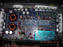
Here is a pic of the board. It has bias test points for all 4 channels, what am I looking for on those. Right now they all read differently. When I adjust the bias pot for channel one, it will pop a 10 amp fuse when adjusting in either direction. With Rockford amps I just put a voltmeter across my .005ohm series resistor in my supply line and watch for the mV's to shoot up, then adjust back a little. I don't see that spike with this amp.
When I load channel 1 with 3 ohms I lose the lower half of the sine wave. Unloaded I can get ~22Vrms out, normal channel is 24.5Vrms.
cory
When I load channel 1 with 3 ohms I lose the lower half of the sine wave. Unloaded I can get ~22Vrms out, normal channel is 24.5Vrms.
cory
Attachments

almost like one of the transistors isnt conducting at all? look at the drivers and double-make-sure
The source resistors appear to be intact but if one is well out of tolerance, that could cause the amp to clip early.
Is the defective channel the only one that causes an increase in idle current when the bias pot is turned clockwise or counter-clockwise?
Adjusting the bias by monitoring the idle current worked on the 2200/2 I repaired.
The bias is important on this amp because (if I'm not mistaken), the bias pot controls the current through the differential amplifier and if there is insufficient current through the differential amp, the following stages can't be driven properly.
In addition to checking all of the driver transistors, check the SMD resistors for that channel on the driver board.
By adjusting the bias pot I was able to get the channel to match the others. I will play music through it all day to see if my adjustments have any bad effects.
- Status
- Not open for further replies.
- Home
- General Interest
- Car Audio
- Power acoustik schematic