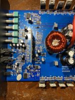
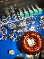
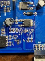
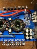
amp has a few snapped power supply fets replaced them. Then I took out the rectifiers and powered it up and a 2x(q3) kept heating up on the same side. Pulled it and noticed 9 volts sitting on pad 1 of q4 (2t)and pad 2 of q16 (2x). On the working side of the amp a resistor pulls the voltage down going to them. On this side it’s not pulling it down. It’s the same before and after r36. And the 9 volts I’m reading is what’s coming off the voltage regulator. I pulled the resistor and the voltage went away. Tested the resistor and its good. I’m lost. Only thing I can e see to pull that down is the resistor that seems to be good. Any help appreciated

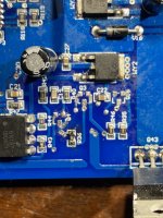
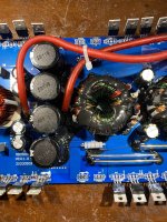


Attachments
Looking at the SLA1500 diagram, which transistors on that diagram correspond to Q3 and Q4 on your amp?
Do you have a good drive signal from both outputs from the driver board?
Working side?
Do you have a good drive signal from both outputs from the driver board?
Working side?
It looks like it’s 4 on that schematic and only 3 on this amp. I’m probably looking at it wrong. Good drive on the writing side and on the bad side I have drive that looks good on one side of r40 and funky on the other
Follow the circuit to find the corresponding parts.
The problem could be on the driver board but that's fairly rare.
Writing side?
The problem could be on the driver board but that's fairly rare.
Writing side?
the voltage comes from the regulator to r36. On the back tab it supplies pin 1 of q3 on the front tab it supplies pin 1 of q4 and pin 2 of q16. With the resistor out I get nothing on those pads
If you can't give me the part numbers from the diagram, this is going to be difficult.
Writing side?
back tab?
If you remove the two resistors that drive pin 2 of the optocouplers, does anything change?
Writing side?
back tab?
If you remove the two resistors that drive pin 2 of the optocouplers, does anything change?
When I removed the resistor I lost drive but still have the extra 9v. Would a 3.9k ohm resistor even be used to drop the voltage?
With those two resistors removed, do you have two good drive signals (pins 01 and 11) from the driver board?
Is pin 5 shorted to pin 8? on the one reading 5v?
Measure both from 6-8 with no power applied. Resistance for each?
Measure both from 6-8 with no power applied. Resistance for each?
Is that ohms, kohms...?
With the resistors for pin 2 of the optocouplers back in the circuit, do you have a square wave on pin 6 of both optocouplers? Both swinging 0 to 5v?
With the resistors for pin 2 of the optocouplers back in the circuit, do you have a square wave on pin 6 of both optocouplers? Both swinging 0 to 5v?
With my multimeter it shows 2.12 volts on both with the multimeter and I can’t tell what it swings from my oscilloscope ain’t right
For the rest of this, I'm going to refer to the circuit board designations on the SLA diagram. You will have to find the corresponding parts on your board.
For Q15 and 16, what is the DC voltage (since your scope is out) with the black probe on the emitter and the red on the collector?
For Q15 and 16, what is the DC voltage (since your scope is out) with the black probe on the emitter and the red on the collector?
- Home
- General Interest
- Car Audio
- Power Acoustik Overdrive 7500
