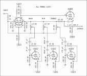
Of course, the pot value is critical, it sets the center frequency with the capacitors used in each of the frequency bands.
yes but capacitors are the same in both circuits.. i've checked it.. only pots are diferrent (10k vs 100k)
Perhaps you could describe what you would like to do so that we may better understand your question?
i am building this circuit but i am comfused about the values of the pots i have to use.. because both circuits i attached are the same, using different pots.. so i am asking if the value of pots its critical...
The main difference between potentiometer values is overlap between bands. As you can see in the two figures, the individual band filter tubes have the same values of passive parts in both diagrams. The 3-band eq has smaller values for the pots because the filters need to cover more frequency range. The smaller pots lower the Q of the filter, which widens the filter's effective range. Likewise, the larger pots increase the Q of each filter to within a narrower range of frequencies. This ensures they don't overlap too much.
The best way to learn for yourself is to build a 3 or 5 band circuit and hear how it changes when the controls are adjusted. Then switch out a single pot with one of a different value and listen to it again. Nothing will get blown except your mind.
The best way to learn for yourself is to build a 3 or 5 band circuit and hear how it changes when the controls are adjusted. Then switch out a single pot with one of a different value and listen to it again. Nothing will get blown except your mind.
You are correct, the pot does not set the center frequency, instead it is the 10k resistor in the gyrator, but the pot value does have an effect on the peaks and valleys, 100k giving a bit more range than the 10k.yes but capacitors are the same in both circuits.. i've checked it.. only pots are diferrent (10k vs 100k)
Ouch!!! what a poor design.
Tubes trying to do (poorly) what SS does easily.
No advantage at all by building an Op Amp and Gyrators equalizer where tubes miss what's needed by far and to boot can add nothing of their magic.
Nothing against tubes per se, just the wrong tool for the job.
The circuit in general looks like a 10X lineal scaling of a very common SS circuit, to the point of using symmetrical +/-150V power rails instead of +/-15V and so on.
Best for this circuit are Ideal Op Amps , to which SS ones are very close real world versions; while tubes are very far from that.
from: Ideal Op-amp Characteristics
* Infinite voltage gain ... NO , think about 50X or so , best reasonably achievable is around 100X or 20dB , any run of the mill 50 cent Op Amp boasts 70 to 90 dB open loop.
* Zero output impedance ..... Op Amps: fractions of an ohm; Tubes: tens of kiloohms, down to hundreds if cathode follower.
* Infinite bandwidth ... well, there tubes are flat, at least within the audio band ; problem is that they have such a low gain that such capability gets unused.
* Zero input offset voltage (i.e., exactly zero out if zero in)
This is the worst offender: an SS Op Amp can have output offset within a couple millivolts of whatever's at the input, and has special pins dedicated to offset zeroing if needed to go down to microVolts, a Tube Op Amp can be lucky if output is less than a few volts away from input.
This circuit could have made sense 60 years ago (or more) when Tube Op Amps were developed for Military and Space use and nothing else was available.
FWIW this is what a real Tube Op Amp looks like:

designed by GENIUS American Designer George Philbrick in 1952

its schematic (notice gas tubes needed to achieve DC level shifting, so output could reasonably follow input within reasonable offset):
compare to 10 (or 3) band equalizer circuit where a crude Tube Op Amp is shoehorned inside a proper SS circuit.
Only possible in a Magazine dedicated to "Tubes everywhere".
Almost forgot: what were original Tube Op Amps developed for?
Think directing one of these against a Soviet Bomber , loaded with Nukes of course, flying towards Washington DC:
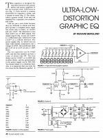
Back to the original question: 10k is ridiculously low, and probably a mistype or transcription error, typical graphic eq pot value is at least 3X the input or feedback resistor value.
Since 33k was used here, a 100k linear pot is fine.
As a side note, best pot resistance curve is "S" curve: log at one end and anti log at the other, for smoothest operation all over the range, but for cost reasons linears are often used.
Here different S tapers are compared to a Linear one:

Tubes trying to do (poorly) what SS does easily.
No advantage at all by building an Op Amp and Gyrators equalizer where tubes miss what's needed by far and to boot can add nothing of their magic.
Nothing against tubes per se, just the wrong tool for the job.
The circuit in general looks like a 10X lineal scaling of a very common SS circuit, to the point of using symmetrical +/-150V power rails instead of +/-15V and so on.
Best for this circuit are Ideal Op Amps , to which SS ones are very close real world versions; while tubes are very far from that.
from: Ideal Op-amp Characteristics
Out of the 5 important goals set above, the only one properly met by tubes is Infinite input impedance , all others fail miserably:The Ideal Op-amp
The IC Op-amp comes so close to ideal performance that it is useful to state the characteristics of an ideal amplifier without regard to what is inside the package.
Infinite voltage gain
Infinite input impedance
Zero output impedance
Infinite bandwidth
Zero input offset voltage (i.e., exactly zero out if zero in).
* Infinite voltage gain ... NO , think about 50X or so , best reasonably achievable is around 100X or 20dB , any run of the mill 50 cent Op Amp boasts 70 to 90 dB open loop.
* Zero output impedance ..... Op Amps: fractions of an ohm; Tubes: tens of kiloohms, down to hundreds if cathode follower.
* Infinite bandwidth ... well, there tubes are flat, at least within the audio band ; problem is that they have such a low gain that such capability gets unused.
* Zero input offset voltage (i.e., exactly zero out if zero in)
This is the worst offender: an SS Op Amp can have output offset within a couple millivolts of whatever's at the input, and has special pins dedicated to offset zeroing if needed to go down to microVolts, a Tube Op Amp can be lucky if output is less than a few volts away from input.
This circuit could have made sense 60 years ago (or more) when Tube Op Amps were developed for Military and Space use and nothing else was available.
FWIW this is what a real Tube Op Amp looks like:
designed by GENIUS American Designer George Philbrick in 1952
its schematic (notice gas tubes needed to achieve DC level shifting, so output could reasonably follow input within reasonable offset):
An externally hosted image should be here but it was not working when we last tested it.
compare to 10 (or 3) band equalizer circuit where a crude Tube Op Amp is shoehorned inside a proper SS circuit.
Only possible in a Magazine dedicated to "Tubes everywhere".
Almost forgot: what were original Tube Op Amps developed for?
Think directing one of these against a Soviet Bomber , loaded with Nukes of course, flying towards Washington DC:
Back to the original question: 10k is ridiculously low, and probably a mistype or transcription error, typical graphic eq pot value is at least 3X the input or feedback resistor value.
Since 33k was used here, a 100k linear pot is fine.
As a side note, best pot resistance curve is "S" curve: log at one end and anti log at the other, for smoothest operation all over the range, but for cost reasons linears are often used.
Here different S tapers are compared to a Linear one:
Jfets could always be swapped out for triodes in the bandpass filters. But they wouldn't keep your hands warm in the winter.
Jfets could always be swapped out for triodes in the bandpass filters. But they wouldn't keep your hands warm in the winter.
🙂🙂🙂
- Status
- Not open for further replies.
- Home
- Amplifiers
- Tubes / Valves
- Pots value in tube equalizer