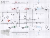
R24, R27 = 100k
C12, c14 = 22uf
R28, r30 = 1M
R18, R25 = 150k
C8, c11, C15, c17 = 33nf
Pot = 1k
R29 = 47k
These are the components around the first stage. Or was it any particular value you need?
C12, c14 = 22uf
R28, r30 = 1M
R18, R25 = 150k
C8, c11, C15, c17 = 33nf
Pot = 1k
R29 = 47k
These are the components around the first stage. Or was it any particular value you need?
AC balance adjustment.
Thanks, could you please elaborate;
As in balancing the two phases in case the tubes differ? Final stage is p-p.
As in balancing the two phases in case the tubes differ?
Yes, it can compensate for tube and component variation, to improve the balance of the input stage.
The adjustment could be made if you input two 1kHz in-phase sine waves, and adjust the pot
for a minimum signal between the two input tube plates. Distortion might be a minimum at that point.
Last edited:
Thanks rayma,
Sounds reasonable.
Any suggestions at which stage measuring should be done when adjusting?
Sounds reasonable.
Any suggestions at which stage measuring should be done when adjusting?
Any suggestions at which stage measuring should be done when adjusting?
Across the plates of the input stage per post #7. You could also try adjusting for a minimum 1kHz harmonic
distortion at the speaker output, and compare the results. They should be close.
Last edited:
If the pot is to change the amplification of the first stage by varying the cathode decoupling, i would expect that C12 and C14 are connected to ground in some way. But in the schematic they are not. Also C12 and C14 are connected to the cathode resistors with their negative sides while their positive sides are connected to the pot, so they are connected to form a non-polarized capacitor, but with a adjustable resistor in between.
I do not understand how the pot could adjust AC-balance because however you set the pot, the change would have the same effect on both triodes.
I do not understand how the pot could adjust AC-balance because however you set the pot, the change would have the same effect on both triodes.
As the signal and the ampstage is symmetrical the point between the capsIf the pot is to change the amplification of the first stage by varying the cathode decoupling, i would expect that C12 and C14 are connected to ground in some way. But in the schematic they are not. Also C12 and C14 are connected to the cathode resistors with their negative sides while their positive sides are connected to the pot, so they are connected to form a non-polarized capacitor, but with a adjustable resistor in between.
I do not understand how the pot could adjust AC-balance because however you set the pot, the change would have the same effect on both triodes.
has "virtual ground". Lack of physical ground might help to make signal more
symmetric if it is slightly assymetric.
Polarity markings are wrong, possibly a drawing error.
Peter and EL504, thanks.
Thanks, ill check over the circuit to confirmed any potential errors in the schematic.
Thanks, ill check over the circuit to confirmed any potential errors in the schematic.
The pot does *not* control the symmetry.
Look at the extremes:
pot = infinite means both caps have no influence at all
pot = zero means both cathodes are connected AC wise
in both cases and anything in between symmetry is not affected.
The pot does control the AC gain albeit just a smidgen.
With the given numbers, 100k cathode resistors (!), the differential gain of the input stage varies by just 1 (one) dB between pot=0 and pot=1k. Approx. from 30dB @ 0 to 29dB @ 1k.
Purpose: Fine tuning of the gain between left and right to make shure that in a stereo both channels play the same volume. Tubes and/or componets have tolerances.
By the way, cap polarity as drawn is correct. With signal the differential potential between cathodes swings from positive to negative, hence the back-to-back connection of the electrolytics.
Last edited:
Sorento,
Lets look again at this circuit in post # 1 above (just a little bit closer).
ECC83: Gm = 1600uMhos, u = 100, (rp = 62.5k).
RL on the plates is 150k.
1/Gm = 625 Ohms
150k/100 = 1500 Ohms
(using the numbers from above).
The each cathode impedance in this circuit is 625 Ohms + 1500 Ohms = 2125 Ohms
The 1000 Ohm gain pot sees 2125 Ohms in series with 2125 Ohms (4250 Ohms).
For all practical purposes, the 100k Ohm resistors fall out of the gain equation (that is why they are so large, which allows them to fall out of the gain equation).
That 1000 Ohm pot changes the gain a fair amount!
I will leave it to you to calculate the gain variation with the pot at 1k, and the pot at 0k.
Hint: The cathodes are in anti-phase
With rp = 62.5k, RL = 150k, and the fact that the cathode 'looking out' sees a range of:
Either 2125 Ohms
Or 3125 Ohms
I do not recommend using back to back electrolytics that way.
That is OK for when the center of them is tied through a resistor to ground.
Want to use electrolytics, then just tie a 1Meg resistor from one end of the 1k pot to the added 1Meg resistor, and the other end of that resistor to ground.
But be sure to reverse the direction of those cathode electrolytics.
Otherwise, use some very large plastic non-electrolytic capacitors.
Expense, size, and weight are required to get better performance.
This is not a $20 quickie preamp.
"Every change requires at least 3 more changes"
Who said that, a Pessimist, a Realist, or an Optimist?
Last edited:
"Every change requires at least 3 more changes"
Who said that, a Pessimist, a Realist, or an Optimist?
An optimally pessimistic realist!!! … ⋅-=≡ GoatGuy ✓ ≡=-⋅
- Home
- Amplifiers
- Tubes / Valves
- Potentiometer function?