Hey,
how about sharing your PCB layouts (jpg, eagle, ...) for the business end of >100W >100kHz in this thread?
The schematics for "classic" class D amps (IR/UcD/SODFA clones etc) most here probably already know by heart, but not so the good PCB layouts 🙂
I already tried the forum search and also googled 'pcb "class d" site:diyaudio.com', but regarding PCB layout pics the results were pretty much nil.
The best discrenible ones were, in the middle of
http://www.diyaudio.com/forums/showthread.php?s=&threadid=82447&perpage=10&pagenumber=4
and this
http://img220.imageshack.us/my.php?image=dsc020231500x11259pl.jpg
And there are a few commercial reference boads with some PCB layout (sometimes in poor quality) shown in the docs. For example:
http://www.irf.com/technical-info/refdesigns/iraudamp1.pdf
http://www.41hz.com/downloads/RB-TK2350.pdf
http://www.zetex.com/3.0/pdf/zxcd100moeval.pdf
http://www.zetex.com/3.0/pdf/zxcd1000.pdf
http://www.41hz.com/downloads/RB-TK2350.pdf
So, you have any good designed-it-yourself >100W >100kHz layout that you'd like to share with class D PCB layouting beginners? 🙂)
- Jan
jwagnerhki said:Hey,
how about sharing your PCB layouts (jpg, eagle, ...) for the business end of >100W >100kHz in this thread?
The schematics for "classic" class D amps (IR/UcD/SODFA clones etc) most here probably already know by heart, but not so the good PCB layouts 🙂
I already tried the forum search and also googled 'pcb "class d" site:diyaudio.com', but regarding PCB layout pics the results were pretty much nil.
The best discrenible ones were, in the middle of
http://www.diyaudio.com/forums/showthread.php?s=&threadid=82447&perpage=10&pagenumber=4
and this
http://img220.imageshack.us/my.php?image=dsc020231500x11259pl.jpg
And there are a few commercial reference boads with some PCB layout (sometimes in poor quality) shown in the docs. For example:
http://www.irf.com/technical-info/refdesigns/iraudamp1.pdf
http://www.41hz.com/downloads/RB-TK2350.pdf
http://www.zetex.com/3.0/pdf/zxcd100moeval.pdf
http://www.zetex.com/3.0/pdf/zxcd1000.pdf
http://www.41hz.com/downloads/RB-TK2350.pdf
So, you have any good designed-it-yourself >100W >100kHz layout that you'd like to share with class D PCB layouting beginners? 🙂)
- Jan
Hi,
Apart from the circuitry, which is an art at itself, laying out PCB's for class D is anything but easy and requires a lot of experience in many fields.
By the time you have gained that, you've spent much money and time. If that is no problem I can only encourage you, otherwise I'd advise to buy an off the shelf unit (I only know the UCD's soundwise - highly recommended) and upgrade / tune these to your own taste.
best
That chip from National and their FET output stage, the LM4652, are on lifetime buy so get them before they are gone. I don't see any date for last possible time to get and don't know how National handles such things but they won't be available forever.
-SL
-SL
Yes off the shelf is usually the simplest or fastest way but it's hardly diyaudio ;-))
LM4651/2, good comment, there indeed is a nice PCB layout on page 19 of http://cache.national.com/ds/LM/LM4651.pdf
As is in a wealth of Tripath eval boards, EB-*.pdf in http://www.tripath.com/downloads/
On the DIY side zkaiser has a really nicely documented project which is more DIY than eval boards: http://www.diyaudio.com/forums/showthread.php?s=&threadid=69349
page two with "multilayer composite print.pdf" PCB layout attached:
http://www.diyaudio.com/forums/attachment.php?s=&postid=787187&stamp=1134300042
Hopefully there are other well documented projects like zkaiser's that include the very relevant PCB layout 🙂)
Got one?
And has anyone made a generic 100..600W@4ohm class D testbed board with only the mosfet and filter section, to which you could then plug various experimental feedback or PCM controllers?
Nobody got a DIY board design? :-|
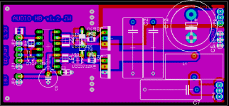
Well here goes my prototype v1.2, IR2110 + 2 x UCC37322 + 2 x IRFB31N20D, single-supply 50..90V, 2-layer PCB (would need 3-layer for dual supply, but 3-layers aren't DIY...). Not so thoroughly tested and scoped yet, there may be some flaws.
Well here goes my prototype v1.2, IR2110 + 2 x UCC37322 + 2 x IRFB31N20D, single-supply 50..90V, 2-layer PCB (would need 3-layer for dual supply, but 3-layers aren't DIY...). Not so thoroughly tested and scoped yet, there may be some flaws.
Attachments
.... more possibles for 100 - 600 watt boards
No diagrams available, lots of pictures, but these have been around for several years and apparently work very well with significant high quality v. power output.
http://aussieamplifiers.com
No diagrams available, lots of pictures, but these have been around for several years and apparently work very well with significant high quality v. power output.
http://aussieamplifiers.com
- Status
- Not open for further replies.
- Home
- Amplifiers
- Class D
- post your business end PCB layouts!