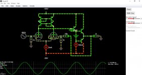
So I have been fooling arround with transistor amps and I had an idea that a DC coupled differential input with triodes in the input instead of transistors could absolutely work.
What I am anticipating is horrid DC drifts and not just as the enviroment changes arround the tube but also with age the tubes degrade in emission. So despite the wacky simulator showing promising numbers where I can compensate the DC offset with the current source of the voltage gain stage In the real world no two triodes will be so well matched as in the simulator BUT...against all the odds...you could have a tube in a transistor power amp that does a lot more than just be a low voltage fed preamplifier.
But considering the reality might just be a total shipwreck I am not suprised why I dont see any documented ideas about this on the internet.
And if you look at the plot of lets say a 12AU7 12AT7 it would be totally doable at these voltages. With probably not bad linearity since the tubes operate in a relatively fixed voltage region with the high gain of the voltage amplifier. So this could be an acceptable scenario where you could use tubes with relatively low voltages. Considering 30V is just about enough for a 12AU7 to conduct a whole 1mA (all though this current doesnt necessarily need to be as high) or the 12AT7 Which can do even 2mA at 30V. So you could avoid high voltages and also use the tube properly (or so to say) (and I dont think a 12AX7 would work at least not with 35V. The model of the tube is supposed to be a 12AX7 but it doesnt copy the plot from datasheets)
Tube officionados gonna hate me but keep in mind this is just an idea that I woke up to from my sleep at 3am, and I will probably never execute it due to the lack of time since im a university student...
Attachments
Last edited:
Which is supposed to be the advantage of such configuration? In Engineering, first it is defined the components, and after, currents and voltages. How could you know that such voltages and currents are the proper ones?
The current mirror you have - Broskie has a set of pages on that 😀 Including this hybrid balanced current mirror (bottom of the page): Broskie OTL Variations & Current-Mirror-Based Push-Pull Buffer
Which is supposed to be the advantage of such configuration? In Engineering, first it is defined the components, and after, currents and voltages. How could you know that such voltages and currents are the proper ones?
I apologise for not clarifying the subject at hand. I would assume so from the load plots of the tubes. That is my reasoning. There are no advantages to this configuration...Neither if youre going from tube to hybrid or from transistor to hybrid. Or at least it doesnt seems to have any pluses.
Its simply an idea that tubes could be used in this speciffic configuration aswell. I guess its essentially making a tube input which would affect the entire amplifier hoping it would add a little "tube stuff" to it.
I dont know if there are any advantages or not. If it makes the sound "warm" or "bad" . It needs further investigation and testing. However Im just putting it here as an idea. You can choose to ignore it or try it and fool arround with it. Would it be research if we knew what were doing?
The current mirror you have - Broskie has a set of pages on that 😀 Including this hybrid balanced current mirror (bottom of the page): Broskie OTL Variations & Current-Mirror-Based Push-Pull Buffer
Actually I ripped these current mirrors from a OP amp of some sort 😀 .
The website shows a lot of interesting ideas however its not quite the same as this
Considering 30V is just about enough for a 12AU7 to conduct a whole 1mA (all though this current doesnt necessarily need to be as high) or the 12AT7 Which can do even 2mA at 30V.
I wonder if you took into account that in order to prevent too much grid current you have to stay away enough from Vg = 0 V.
With a 12AU7 at 1 mA per section Vg would be about - 1.5 V at Va = 30 V. That might still work as far as grid current is concerned.
But with a 12AT7 at 1 mA per section Vg would have to be about - 0.6 V at Va = 30 V. I would think that this is too low. Some grid current will flow.
I dont think grid current would be a concern unless its unhealthy for the tube. Its nothing incredibelly high to disturb the functionality of the circuit.. However I can go lower in current.. Perhaps 700uA or 500uA assuming the voltage amplifier stage has enough ampliffication it wont affect anything really. Im not really shooting for high impedances here.
Well, the very first operational amplifiers were built with tubes, including a differential input,so .... 🙂

Actually I ripped these current mirrors from a OP amp of some sort 😀 .
The website shows a lot of interesting ideas however its not quite the same as this
Well, the very first operational amplifiers were built with tubes, including a differential input,so .... 🙂
Indeed - I started with that schematic for the op-amp sections for my V2 amp 🙂
Differential pair (note that one does not have a resistor for maximum gain), then a amp as SE and then a cathode follower for low impedance output. A negative feedback from the output to the amp and differential pair. +320 to -320V.. so nice and friendly 😀
I then switched to differential input and output - the output means you end up with three tubes per opamp.
I wonder if you took into account that in order to prevent too much grid current you have to stay away enough from Vg = 0 V.
With a 12AU7 at 1 mA per section Vg would be about - 1.5 V at Va = 30 V. That might still work as far as grid current is concerned.
But with a 12AT7 at 1 mA per section Vg would have to be about - 0.6 V at Va = 30 V. I would think that this is too low. Some grid current will flow.
I have to return to your reply, you were absolutely correct and it did cause problems. Grid current is apparently also modelled into the simulator and it seems that you were absolutely correct about it. So I either build a 35V+/- modest power amp with a 12AU7 hoping I wont run into grid current problems and or I just decide to go for a much bigger amplifier that would be powered 50V+/- so the tube has more breathing roon.
- Home
- Amplifiers
- Tubes / Valves
- Possibly the most "why would you" kind of idea for a hybrid amp