I have to switch over to graveyard shift for one night tomorrow so I am pulling some late hours at the computer to switch over my body clock. I was running some spice sim's for my edification and noticed something that I think may point to an advantage of gNFB over local.
We are all familiar with some of the advantages of local FB on the output stage but as I was playing I noticed that the local FB (plate to plate) by virtue (or vice perhaps) of reducing the gain of the output stage reduced the maximum possible output power considerably because driving the grid right up to 0V resulted in less output voltage swing given the same OPT primary impedance.
With gNFB the gain of the output stage is not reduced and so full output is still available as long as the input signal can be increased enough to compensate for the loss in overall gain.
This brought a couple of questions to mind.
1) Shouldn't this have been obvious to me without having to run simulations? 😉
2) Is it therefor customary to use a different OPT impedance for local feedback applications?
reducing the gain of the output stage reduced the maximum possible output power considerably because driving the grid right up to 0V resulted in less output voltage swing given the same OPT primary impedance.
How much local NFB you had ?
How much max. output was decreased due to local NFB ?
What does your similation give if you lower the g1 voltage ?
Maximum power output is at clipping, not an arbitrary voltage threshold. A threshold which depends on how the circuit is wired. Vgk = 0 isn't a magical point of clipping; that depends on your load resistance (which you usually pick so it is). Class 2 amplifiers, obviously enough, don't clip at Vgk = 0; most class 1 amplifiers do, at or below 0V.
Depending on what resistor values you used, your driver might not even be able to supply enough voltage to drive the output to clipping.
FYI, local feedback is preferred because it improves bandwidth and phase margin independent of the number of stages. With the improved response per stage, you could then cascade stages and add more NFB around groups of stages or globally, with much improved performance over the case of the same total amount as gNFB.
Tim
My experience with the red board reveals no major difference in maximum power output with no feedback, GNFB, or local Schade feedback. Given a driver capable of feeding the output tube all it needs I find only 3 things that limit the maximum power output. The choice of output tube. Obviously plate dissipation and voltage ratings are important, but so is peak current carying capability and saturation characteristics. For a given tube the only variables are load impedance and plate voltage.
The use of local feedback will indeed reduce the gain of the output stage. The driver tube must be capable of supplying the increased drive voltage demands without undue distortion. The use of GNFB will reduce the gain of the entire amplifier. In either case 14 db of feedback will reduce the gain of the entire amp by 14db. With GNFB the gain of the driver and the output stage is reduced. The amount of reduction in each stage depends on the individual stage gains. With Schade feedback all 14db of gain reduction will come from the output stage, demanding 14db of additional headroom in the driver.
14db is probably too much to ask from the driver stage. My experiments with the red board use 6 to 8 db of Schade, GNFB, both, or neither. I find that the amp will measure about the same using local or GNFB. I get better distortion numbers from idle to just below clipping with both feedback paths enabled. In listening tests with dynamic music I find Schade feedback only preferrable. GNFB alone is OK, but both feedbacks together take all of the life out of the music.
With GNFB the gain of the driver and the output stage is reduced.
I think this is not the case in typical GNFB arrangement.
Can you give an example where the above takes place?
I have documented one of my PP-amplifiers with 14 dB GNFB and without.
The amplifier is conventionel with 6L6 PP-output stage, 6N7 long tailed pair phase splitter and 6SL7 voltage amplifying stage.
GNFB is fed normally from the secondary of the OPT to the cathode of the voltage amplifying stage.
The AC-voltage measurements show that when GNFB is activated, the gain of the voltage amplifying stage only is reduced from 32 dB to 18 dB, i.e. by the amount of GNFB.
The gain of all the other stages remain unchanged.
Something else is going on with my simulation that is making it hard to determine exactly what is going on.
I realized this morning that I was accidentally running with the outputs connected triode mode but I was getting 15 or so watts (5V+ peak into 4 ohms) before clipping which occured when the driver output voltage was equal to the bias voltage of the outputs. Clearly this is way too much power from trioded EL84s.
This morning I redrew it for pentode mode. This allowed over 10V peak into 4 ohms. Again way to much. Something is goofy either with the Koren models I am using or my transformer model or something.
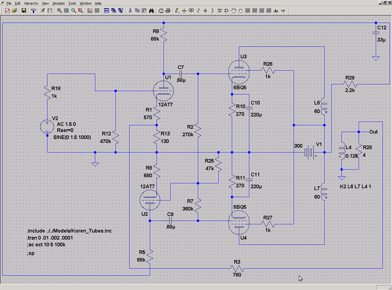
The topology is Floating paraphase with 12AT7s using 68K plate load and about 1.6V cathode bias (680 ohms unbypassed). The output stage has 270 ohm resistor bypassed by 220uf caps on each EL84 cathode (10.5V cathode voltage). Power supply is 300V with the screen taken from the same B+ with 1K dropping resistor. The DC voltage drop at the screen is only about 1V.
The OPT is simulated with the two sides of the primary spec'ed at 60H and 1ohm DCR. Secondary is 0.125H and 0.1ohm DCR. K=1. My understanding is that this should be a bit over 8K P-P anode load.
I ran the simulation to get the maximum unclipped output then I added 270K plate to plate to my original model (this was triode connected remember) the output level for the same input dropped by a factor of five but the signal to the EL84 grids was still at the maximum before clipping (about 10V peak) so any further increase in input voltage just drove the outputs into clipping with no increase in output.
I switched to gNFB by dividing the input tube's cathode load into two with an upper R of 570 ohms and a lower of 130 ohms (using 110 ohms unbalanced the bias due to the parallel Rfb). I adjusted the value of Rfb to get the same overall gain reduction and ended up at, IIRC, about 760 ohms for Rfb. In this case the gain of the input/PI stage was reduced so that the input to the EL84 grids was reduced by a factor of 5. For this reason I could increase the input voltage to the point were the grids of the EL84 were again driven to the maximum 10V. The output power was now restored to its original value.
So I have two things going on. One something is wrong with the power output levels that I am getting and two is that the local feedback is reducing the total available power out. I suppose that I could use a follower between the PI and the outputs to allow some grid drive but this would also increase the potential output without FB.
BTW, I am calculating the output power by (Vpeak*1.4)^2/4
Any enlightenment you can offer would be appreciated.
I realized this morning that I was accidentally running with the outputs connected triode mode but I was getting 15 or so watts (5V+ peak into 4 ohms) before clipping which occured when the driver output voltage was equal to the bias voltage of the outputs. Clearly this is way too much power from trioded EL84s.
This morning I redrew it for pentode mode. This allowed over 10V peak into 4 ohms. Again way to much. Something is goofy either with the Koren models I am using or my transformer model or something.
The topology is Floating paraphase with 12AT7s using 68K plate load and about 1.6V cathode bias (680 ohms unbypassed). The output stage has 270 ohm resistor bypassed by 220uf caps on each EL84 cathode (10.5V cathode voltage). Power supply is 300V with the screen taken from the same B+ with 1K dropping resistor. The DC voltage drop at the screen is only about 1V.
The OPT is simulated with the two sides of the primary spec'ed at 60H and 1ohm DCR. Secondary is 0.125H and 0.1ohm DCR. K=1. My understanding is that this should be a bit over 8K P-P anode load.
I ran the simulation to get the maximum unclipped output then I added 270K plate to plate to my original model (this was triode connected remember) the output level for the same input dropped by a factor of five but the signal to the EL84 grids was still at the maximum before clipping (about 10V peak) so any further increase in input voltage just drove the outputs into clipping with no increase in output.
I switched to gNFB by dividing the input tube's cathode load into two with an upper R of 570 ohms and a lower of 130 ohms (using 110 ohms unbalanced the bias due to the parallel Rfb). I adjusted the value of Rfb to get the same overall gain reduction and ended up at, IIRC, about 760 ohms for Rfb. In this case the gain of the input/PI stage was reduced so that the input to the EL84 grids was reduced by a factor of 5. For this reason I could increase the input voltage to the point were the grids of the EL84 were again driven to the maximum 10V. The output power was now restored to its original value.
So I have two things going on. One something is wrong with the power output levels that I am getting and two is that the local feedback is reducing the total available power out. I suppose that I could use a follower between the PI and the outputs to allow some grid drive but this would also increase the potential output without FB.
BTW, I am calculating the output power by (Vpeak*1.4)^2/4
Any enlightenment you can offer would be appreciated.
Last edited:
It's been my experience that local feedback (plate-to-plate) actually decreases the driver stage gain, not the output stage gain. The output stage still requires the same amount of drive voltage and it's power output should remain appox equal to open loop.
The potential problem which sounds like you are experiencing is that as you increase the feedback ratio, the AC impedance seen by the driver proportionally decreases (wich is why gain decreases). There comes a point where the feedback ratio is so high, the driver is unable to swing the required voltage (because its working into an impedance that is too low).
The potential problem which sounds like you are experiencing is that as you increase the feedback ratio, the AC impedance seen by the driver proportionally decreases (wich is why gain decreases). There comes a point where the feedback ratio is so high, the driver is unable to swing the required voltage (because its working into an impedance that is too low).
Last edited:
I have no experience with simulation whatsoever, however the specs of the OPT seem strange to me. Normally it is specified in primary / secondary impedance or winding ratio.
60H per primary side to 0.125H for the secondary is 7k68 plate - plate primary impedance to 8 ohms secondary.
However 1 ohm DCR per primary side is far beyond reality; that should be at least 60 to 70 ohms for a good quality OPT, but maybe this has nothing to do with the sim?
60H per primary side to 0.125H for the secondary is 7k68 plate - plate primary impedance to 8 ohms secondary.
However 1 ohm DCR per primary side is far beyond reality; that should be at least 60 to 70 ohms for a good quality OPT, but maybe this has nothing to do with the sim?
Any enlightenment you can offer would be appreciated.
If you had a real amplifier with such phenomenon, it would be possible to give some opinion about the reasons for unproper operation.
But I see that is quite useless to try to guess what is wrong with your simulation since there is some one thousand possibilities.
Jeb, the impedance may be an issue now that you mention it. The Rg for the outputs is only 270K and plate load of 68K on the driver. It also may be that by coincidence the gain of the driver is marginal to begin with (probably about 10).
Pieter, To model a transformer you have to specify coils with a mutual inductance and the inductance ratio should be equal to the turns ratio squared IIRC. On a PP OPT each phase of the primary is spec'ed with 1/4 of the total P-P inductance. You are right about the DCR of course.
I will play with it a little more next week. I am doing this exercise primarily because I was interested in the floating paraphase and how it might respond to various FB strategies. I might try it with 12AX7 also and see if it works a bit better also. Might also be interesting to try a small signal pentode just for giggles. 🙂
I appreciate you guys helping me think this through.
.It's been my experience that local feedback (plate-to-plate) actually decreases the driver stage gain, not the output stage gain. The output stage still requires the same amount of drive voltage and it's power output should remain appox equal to open loop
Yeah, I don't know what I was thinking yesterday. I am 1200 miles from home and was recovering from food poisioning.
The gain of the circuitry inside the feedback loop should not change as the feedback is applied. The gain reduction takes place at the summing junction where the feedback is applied. This assumes ideal conditions. In a silicon opamp with 100+ db of open loop gain and a linear summing junction things are close enough to ideal for these assumptions to apply.
In a tube amp where open loop gain is limited and the summing junction is not ideal the point where the feedback gets applied may not be a single point. The LTP summing junction does a good job if the signal and feedback are applied to opposing grids. The usual single gain stage with signal applied to the grid and feedback applied to the cathode may see some modulation of the input impedance if grid current is approached. These schemes are however close enough so that we can assume that most of the gain reduction occurs in the input stage where the summing takes place.
In the typical Schade feedback circuit the summing junction is somewhat spread across two stages, both of which can be non linear. Assuming the usual resistor from the plate of the output tube to the plate of the driver, there is a voltage divider that determines the feedback ratio. The "Schade" resistor forms a divider against the parallel combination of the resistor from the output tube grid to the bias supply, the driver plate load resistor, the Rp of the driver tube, and the grid impedance of the output tube.
The two fixed resistors are constant and known. The Rp of the driver is somewhat constant and fairly high in a pentode. The Rp of a triode is fairly low and varies with signal level in a triode. This is why many experts state that Schade feedback will not work with a triode driver. The grid impedance of the output tube should be near infinite until the grid is driven positive, then it approaches zero.
Note:
I have built several working amps with Schade feedback applied to a triode driver despite being told that it won't work. Schade will also work in triode LTP drivers in P-P amps. I made a really nice sounding 3 stage amp with cross coupled "Schade" applied across two stages.
In the ideal world (pentode driver) the summing junction is the plate load resistor and the feedback resistor. In reality the feedback voltage appearing at the plate of the driver tube will affect the operation of the driver tube itself. The output tube will have some grid current, but the effect is minimal until near zero bias is reached. In the positive grid region the feedback and the drive voltage stare to get shunted to ground. In the red board I have observed up to about +20 volts on the grid without undue distortion. Yhis is dependent on choice of driver tube. The best choice so fat is the 6GU5 hexode!
This makes an exact determination of just where the summing junction is under all conditiona nearly impossible. I am sure it will give the simulator fits. I am assuming that LTspice is the simulator here? I have used it and it will simulate the Simple SE perfectly. Many of my other circuits will drive it nuts. I have found it useless whenever positive grid operation or screen drive is attempted. I would think it might have a problem with Schade applied to to a triode driver too. I know it's not the simulator, it is the fact that most tube models were not meant to simulate grid current, screen drive, or simulated George testing.
Theories:
It is possible to isolate the output tube grid effect by using a mosfet follower to feed the grid all of the current it can eat. It is also possible to use a mosfet follower to isolate the feedback summing junction from the driver tube. This would make triode driver use easy. It is possible to apply the feedback to G3 of a dual control pentode like the 6AS6 or a mixer tube like the 5915 or 6BE6. It is possible to apply the feedback to G2 of a conventional pentode. My experience with mixing mosfets and tubes in LTspice has been a mixed bag. I am sure that the dual control stuff won't simulate even if a model can be found. To test my theories a breadboard is under construction. I call it the Grand Unified Theory breadboard or GUT board. Who knows when I will finish it though.
If you are using LT spice and care to share your ASC and INC's I (and others) may have time to play with them in the next few days.
That doesn't sound fun. I had the stomach flu a few weeks ago. Similar symptoms.I am 1200 miles from home and was recovering from food poisioning.
I will play with it a little more next week. I am doing this exercise primarily because I was interested in the floating paraphase and how it might respond to various FB strategies.
If your floating paraphase is directly pushing the output tubes, global (returned to input triodes cathode) is probably your best bet.
IMO the best config is triode with unbypassed cathode for the input and pentode for the slave (for lack of a better word).Might also be interesting to try a small signal pentode just for giggles.
That doesn't sound fun. I had the stomach flu a few weeks ago. Similar symptoms.
Fortunately the real nasty stuff only lasted for about 12 hours. The lack of sleep resulted in almost two days of general fogginess and stupidity. I finally got to go outside and play in the snow today. Back to Florida when the weather permits the long drive, probably Wednesday.
re Tubelab:
"The Rp of a triode is fairly low and varies with signal level in a triode. This is why many experts state that Schade feedback will not work with a triode driver. "
I think there may be a good case for a triode driver with Schade plate to plate feedback if it's set up properly:
If the fixed resistor loading to Rp ratio of the triode driver is in the same ratio as the OT reflected primary loading is to the output tube Rp (at idle for class A, or at 1/2 on for class AB), then the two stages (driver and output) distortion curves should cancel out to 1st order (2nd Harmonic) just like a differential stage. Around the idle/null point, as the driver Rp drops it puts out more grid drive in compensation for the output tube Rp increasing from turning off. It would be tough to match up a triode drivers low Rp with pentode outputs high Rp that way obviously. But triode('d) outputs should sail.
The RH type Schaded amplifiers probably appoached this, the pentode output was "sorta" trioded by using a high value screen resistor. The 12AT7 driver was naturally high 2nd harmonic, so making it easier to play the curves off against each other.
Probably not a working distortion cancelling scheme though for a differential triode driver stage, since the drivers would already be cancelling each others distortion to 1st order and the driver Rp's are averaged too. But then the averaged driver Rp's look fairly constant, like with pentode drivers only lower, so still a workable scheme (ordinary neg. feedback), just not active complementary-distortion anymore.
Last edited:
Hmm.. Now I can't duplicate my original results with the Schade FB. I must have had some other mistake in the schematic that I accidentally corrected. Now the Schade isn't working at all. 😀
Now I am getting results more like I expected. The signals at the grids of the outputs are wildly different in a circuit that had very good balance at that point with no FB and with global FB. Interestingly the signal at the OPT secondary is not bad even though the signal at the inverted driver output is quite ugly.
Given that the floating paraphase has an inner FB loop for the inverter I expected to get something more like this when applying shade to both. For interest sake I also tried it with the old fashioned plain paraphase but it also gave similar (though not identical) results.
I also noted that with the global FB scheme at the level I was running I reached maximum input tube grid swing (1.5 volts peak) at about the same level that I reach maximum output tube grid swing (10.5 volts peak).
So it looks like Schade is not a good choice for local FB on paraphase type circuits. Possibly cathode FB would be possible if an appropriate OPT was available.
Here are the asc and inc files for the global FB version that seems to work pretty well. I had to change the file names to get them to upload. Just remove the txt and change the underscore to dot.
I still have no idea why the simulation is telling me that I can swing over 11V peak into a 4 ohm load though.
Attachments
Putting Schade Fdbk to only one of the paraphase plates will lower the gain there significantly and unbalance the signal within the splitter. You will probably have better luck with Schades to both sides of the splitter. But it will still take more signal to the inverter side grid to drive the low impedance of the Schaded plate. I assume the outputs are running in class A. Class AB could further mess up the inverter with somewhat varying loads.
Actually when I had it hooked up with schade instead of global it was on both sides. It is bias AB but even at low signal levels it was severely unbalanced. To be clear, the changes I made to the above for schade was to delete R3, change R13 to 110 ohms and put a 270K (tried larger values too) between the plates of the 6BQ5 and 12AT7 on each side (U1 to U3 and U2 to U4).
The schematic shown above is with the global FB and it simulates very well.
The schematic shown above is with the global FB and it simulates very well.
mashaffer,
Remove R25. It's attenuating the signal to the inverters grid. Add a pull down resistor to the grid of each output tube.
Remove R25. It's attenuating the signal to the inverters grid. Add a pull down resistor to the grid of each output tube.
That's thinking too much like he's using a real balanced driver topology. Floating paraphase is a complete different animal. Due to it's follow-the-leader behavior, only feedback to the input tube really matters. The inverter tracks the output of the input tube, so it will mimic the behavior that balanced feedback would provide when applied to balanced drivers. Also remember that the plate impedance of the inverter is so low (because it utilizes 100% feedback). Applying feedback to it's plate resistor has little effect (even with un bypassed cathode resistor). If anything I'd suspect applying feedback to the input and inverter would make balance worse.Putting Schade Fdbk to only one of the paraphase plates will lower the gain there significantly and unbalance the signal within the splitter. You will probably have better luck with Schades to both sides of the splitter
Last edited:
I assume the outputs are running in class A. Class AB could further mess up the inverter with somewhat varying loads.
That is a good point. I was assuming class A as well. For class AB, using a Circletron output would be the only way I can think to pull off that type of feedback using a paraphase front end.
It's probably best to stick with global for paraphase design. Not to mention, paraphase has poor PSRR (yes, even the floating variant) so it's good to have the extra filtering that adding an additional decoupling network can supply (when compared to tying it directly to the output stage power supply).
Last edited:
- Status
- Not open for further replies.
- Home
- Amplifiers
- Tubes / Valves
- possible advantage to global???