Recently I tricked myself into buying a subwoofer but it was for car audio, now I'm trying to not having to buy it from the ebay seller...
It did push me to have a look at what I have available in my own garage and I wondered what you guy's might think about using them for.
I have two 8" drivers that came out of old Bose 301 MKII boxes
Two 10" Monacor SP-250P drivers
Four 15" drivers. Only three work OK, can't view the model number now, not home at the moment but not important, nowhere to be found on the net, fs is 20hz, 100W, polypropylene cone, small magnet.
I have been pondering about how to use them but I just can't decide.
Multiple subs is something that I certainly consider.
Amps that I have: Velleman K4020, Pioneer A-656
And a crossover XEC-505 from Sony
Some coils for passive filtering.
Thanks!
good idea with the multiple subwoofer setup. play around with location and see what you get. maybe put the biggest ones in a corner of the room and scatter the other ones around the walls.
first test on the way...
Hello,
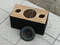
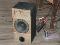
I pulled out some old DIY boxes I built about 25 years ago🙄
It felt good to see them again, fun times!
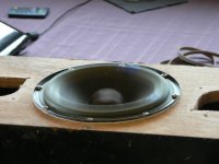
After pulling out five skeletons from death rats 😱 and cleanup, I installed the 8" from Bose (with repaired surround) and closed the holes from the Ti-tweeters.
Now I'm waiting for the wood-glue to cure.
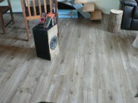
This little closed box is going in place of the currently used sub, so I can compare to the sound prior to this sub. Then I'm going to experiment with some coils, maybe even convert this box in a bass reflex.
Volume is about 18l. (0.64ft³)

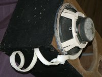
air seal

vibes at about 30W 50hz sine wave (free air because of the holes, short burst for the photo 🙂)

glue curing

It doesn't get any cheaper!... 😉
Hello,
I pulled out some old DIY boxes I built about 25 years ago🙄
It felt good to see them again, fun times!
After pulling out five skeletons from death rats 😱 and cleanup, I installed the 8" from Bose (with repaired surround) and closed the holes from the Ti-tweeters.
Now I'm waiting for the wood-glue to cure.
This little closed box is going in place of the currently used sub, so I can compare to the sound prior to this sub. Then I'm going to experiment with some coils, maybe even convert this box in a bass reflex.
Volume is about 18l. (0.64ft³)
air seal
vibes at about 30W 50hz sine wave (free air because of the holes, short burst for the photo 🙂)
glue curing
It doesn't get any cheaper!... 😉
Attachments
Wouldn't it be better to use the small ones in corners because of the reinforcement? And the bigger ones along the wall or as a table?
Did a sine wave at 16.4V and it drew only 0.9A (laying on its back)
So at 50hz the system has a resistance of:
16.4V/0.9A=18.2Ω
don't know what this means yet, will have to use an amp and resistor with a freq gen on it.
Did a sine wave at 16.4V and it drew only 0.9A (laying on its back)
So at 50hz the system has a resistance of:
16.4V/0.9A=18.2Ω
don't know what this means yet, will have to use an amp and resistor with a freq gen on it.
Last edited:
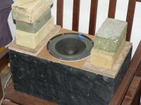
Just wired up the amp with an 8Ω resistor in series, to measure resonance.
The box is standing on the floor in the middle of the room, what is this called, 'half space'?
Highest voltage on the driver while lowest voltage on the resistor is resonance, in this case: 7.2V on the driver, 2V on the resistor.
The system has a resistance of:
8x7.2/2=28.8Ω at the frequency of 64hz
Not bad for an 18l sealed box I think...
Attachments
Last edited:
At 80hz : on the R= 3.6V, driver= 6.5V
- 8Ω / 3.6 * 6.5 = 14.44Ω at 80hz
This means, if I want to use a 6th order passive filter, I need a coil that's:
28.6mH! 😱
Am I doing something wrong here?
- 8Ω / 3.6 * 6.5 = 14.44Ω at 80hz
This means, if I want to use a 6th order passive filter, I need a coil that's:
28.6mH! 😱
Am I doing something wrong here?
You might better off considering a plate amp in place of the passive XO. The caps and coils can sure add up quickly.
Wouldn't it be better to use the small ones in corners because of the reinforcement? And the bigger ones along the wall or as a table.
The big ones in the corner is supposed to give you the bulk of the bass, the smaller ones can fill up some modal holes in the resulting response. corner placement, since thats the position that excites the maximum of modes. with that approach, the big one should be considerably louder than the support subs, so using the biggest one is the way to go. but in the end, you have to see (measure) what works and what not.
Thanks, I'll keep that in mind.
I did some measurement on a know inductor of 3.5mH.
with the dummy load of 8Ω in series, they both had the same voltage at 252hz.
But if I calculate what it should be, I get 365hz at 8Ω for 3.5mH
What am I missing here?
I did some measurement on a know inductor of 3.5mH.
with the dummy load of 8Ω in series, they both had the same voltage at 252hz.
But if I calculate what it should be, I get 365hz at 8Ω for 3.5mH
What am I missing here?
Did a swap with the Deathbox and I had to give 7dB more power to this box to experience the same bass. This was to be expected.
If I was to change this to a BR, what frequency tuning should I use giving the known value of 64hz resonance in the sealed cab?
If I was to change this to a BR, what frequency tuning should I use giving the known value of 64hz resonance in the sealed cab?
Post #6
Hi ßart West-VL.,
In addition to the inductive reactance you also have the coils (DC) resistance.
Regards,
Hi ßart West-VL.,
In addition to the inductive reactance you also have the coils (DC) resistance.
Regards,
Oliver, the resistance is not measurable, not even if I put all four of them in series, two of them are rated 14A continuous use.
But what would a bit of resistance mean to the freq curve?
thanks
But what would a bit of resistance mean to the freq curve?
thanks
Posts #9, 11 and 12
Hi Bart,
I was referencing the wrong post in the title of Post #11, I ment Post #9. Your calculation looks OK, if the coils resistance is minimal, and your resistor is 8 Ohms, that basically leaves you with a bad measurement or wrong frequency meter?
Regards,
Hi Bart,
I was referencing the wrong post in the title of Post #11, I ment Post #9. Your calculation looks OK, if the coils resistance is minimal, and your resistor is 8 Ohms, that basically leaves you with a bad measurement or wrong frequency meter?
Regards,
Hi!
Sorry I couldn't respond earlier, wasn't home when I read up on DIYaudio.
Uhm... How did I get to these results... I'll try to explain my logic approach
I assume that, when the resistor and the inductor get the same voltage, that means they are at the same resistance (8Ω). So I'm not using a frequency meter but I read it from Sinegen. (frequency generator on the laptop)
So if they both get the same voltage drop at a given frequency, that means they have the same resistance.
This was at 252hz.
But I KNOW the value is 3.5mH and if I calculate what te frequency SHOULD be at that same resistance, I get 365hz as a result.
I really want to understand this, there must be something I'm missing.
Thanks!
Added a port to the sealed 8" test-box.
Added a port of 127mm and 50mm diameter.
The volume is about 18l.
Calculations say that's about 45hz resonance.
Measurement says 41hz. @9.3~Ω
Highest impedance at the low side=@20hz =~17Ω
Highest impedance at the high side=@73hz =~22.8Ω
Impedance is then dropping till 160hz (6.5Ω) is reached.
Then raises again till 2800hz (32.4Ω) is reached.
After that, I think inductance has to much influences.
Comments?
edit. Did a test at 26V at resonance, 41hz (9.3Ω) I think that is 73W real power. 😀
Didn't hear any noise except port noise. 🙄
Attachments
Last edited:
- Status
- Not open for further replies.
- Home
- Loudspeakers
- Subwoofers
- Possibilitys with different sorts of drivers? 8" 10" 15"