Can I replace in generall power tubes (6550, EL34, 6C33C) trough high voltage mosfets arround Uds 1000V?
If yes, what value of resistance I must choise for the transformator windings (ultralinear, PPP) and what value of resistance I must choise for the source resistor to create the internal tube resistance (OTL)?
Because the value of source resistance is much higher compare to typical solid state amps, there are the possibility to use many parallel devices.
Has anyone this one already tested?
Thank you very much for your advices.
MOSFETs have huge input capacitances, thermal dependencies, so no direct replacement is possible, but you can build a "tube" that has pentode characteristics, gm of amperes per volt, and couple of hundred watt of dissipation. Here is my example (obsoleted already, so I post it here):
http://wavebourn.com/forum/download.php?id=137&f=7
http://wavebourn.com/forum/download.php?id=137&f=7
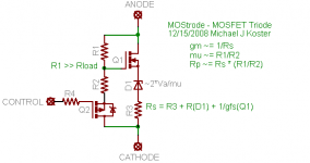
This is a big subject: And the only easy answer I know revolves
around faking the internal feedback mechanism of the Triode.
Sometimes the best way to "fake" it is with a small triode as
both the input buffer for high impedance and the reference
model for Mu.
If you were to place the base to emitter junction of a bipolar
transistor in series with your reference Triode's cathode, you
have a Triodlington. Current is multiplied roughly by Beta, but
plate voltage is still controlled almost entirely by the internal
feedback mechanism (Mu) of the tube. If plate and collector
are strapped together, the transistor becomes slave to this
feedback.
You can do the same with a MOSFET, but need to add one
resistor across the Gate to Drain.
Now, if you really wanna fake a Pentode, beam power type,
for UL or whatever... I don't know if enough voltage feedback
gets through a normal pentode's plate resistance to abuse a
small one as a feedback reference. I got a feeling that straight
up Pentodlington based on a Pentode wouldn't work..
Might just maybe could fake your way there with a Cascode
of two Triodlington type emulators???
Peter;
it sounds nice theoretically, but practically triode with BJT or MOSFET is not practical due to huge resulting Miller capacitance. Also, a simple resistor between gate and source does not work because of thermal dependence and much higher forward transconductance of MOSFET VS tube. That's why I had to use a pentode and sophisticated thermal compensation through gyrator.
it sounds nice theoretically, but practically triode with BJT or MOSFET is not practical due to huge resulting Miller capacitance. Also, a simple resistor between gate and source does not work because of thermal dependence and much higher forward transconductance of MOSFET VS tube. That's why I had to use a pentode and sophisticated thermal compensation through gyrator.
Thanks for your first comments
The high capacity (additional non-linear) was for me the main reason MOSFETs as replacement for tubes to use. However, only in a CSPP topology (Circlotron) and only as a source follower (gain less than 1). The whole thing should be placed outside a NFB loop (very important to prevent sawtooth waveforms and TIM).
In a simulation I get very good THD results (see PDF) - If I would have the time, I would build such a power amp device - I'm almost sure that it is possible also in real life excellent sonic results. Maybe another of the members perhaps have time to build such a part - but it should not be a beginner - 2x 400 VDC are very danger.
In the first step, I recommend a voltage from 2x50V to use. The power output amounts now only 1/32, but is enough for checking the sound quality.
At bottom the results of my idea - but please note, that by this simulation all capacitors and resistors so as the voltage source (power supply) and input source (signal generator) are idealized (i. e. no internal resistance by the power supply). In additional there are no lead respective wire inductance and spread capacitance through PCB layout.
Only the effects of transistor spice models so as the pure circuit there are to see.
Idea for CSPP 2x400V, idle power: 13x80mA = 832W, input=18V, output=10V
1) schematic
2) frequency response
3) THD 10 KHz (lin) third harmonic 0,73mV
4) THD 1 MHz (lin) third harmonic 2 mV
5) THD 1 MHz (log)
6) THD 10 KHz (log)
Wavebourn said:MOSFETs have huge input capacitances, thermal dependencies, so no direct replacement is possible, but you can build a "tube" that has pentode characteristics, gm of amperes per volt, and couple of hundred watt of dissipation. Here is my example (obsoleted already, so I post it here):
http://wavebourn.com/forum/download.php?id=137&f=7
The high capacity (additional non-linear) was for me the main reason MOSFETs as replacement for tubes to use. However, only in a CSPP topology (Circlotron) and only as a source follower (gain less than 1). The whole thing should be placed outside a NFB loop (very important to prevent sawtooth waveforms and TIM).
In a simulation I get very good THD results (see PDF) - If I would have the time, I would build such a power amp device - I'm almost sure that it is possible also in real life excellent sonic results. Maybe another of the members perhaps have time to build such a part - but it should not be a beginner - 2x 400 VDC are very danger.
In the first step, I recommend a voltage from 2x50V to use. The power output amounts now only 1/32, but is enough for checking the sound quality.
At bottom the results of my idea - but please note, that by this simulation all capacitors and resistors so as the voltage source (power supply) and input source (signal generator) are idealized (i. e. no internal resistance by the power supply). In additional there are no lead respective wire inductance and spread capacitance through PCB layout.
Only the effects of transistor spice models so as the pure circuit there are to see.
Idea for CSPP 2x400V, idle power: 13x80mA = 832W, input=18V, output=10V
1) schematic
2) frequency response
3) THD 10 KHz (lin) third harmonic 0,73mV
4) THD 1 MHz (lin) third harmonic 2 mV
5) THD 1 MHz (log)
6) THD 10 KHz (log)
Attachments
Wavebourn said:Peter;
it sounds nice theoretically, but practically triode with BJT or MOSFET is not practical due to huge resulting Miller capacitance. Also, a simple resistor between gate and source does not work because of thermal dependence and much higher forward transconductance of MOSFET VS tube. That's why I had to use a pentode and sophisticated thermal compensation through gyrator.
Where in either of these circuits is there an increase in Miller?
There is definately a huge increase in transconductance. And
if transconductance is the limiting factor, thermals will make
a big difference. But if Mu is the limiting factor...
Matters little the thermals or linearity of either BJT or MOSFET.
The tube is watching the voltage of both parallel anodes, and
applying the rule of Mu. Neither type of sand likely to run away
or be non-linear when locked down by 1/(Mu-1).
The Pentode model would be a cascode of Triodlings, possibly
with different mu needed for screen and G1. That requirement
alone might make the circuit impractical...
Attachments

regarded the parallel devices - this approach is also to find by "Tim de Paravicini's" V20 (V 20) - go toWavebourn said:I would call it Super-cyclotron. Good luck!

http://www.stereophile.com/integratedamps/1099ear/
and
http://www.envogue-24.de/Neue Seiten/ear/V20vollv.html
for more information
The best tube amplifier that I ever heard. Especially for tweeter driving in bi- resp. multi-amping systems.
In opposite to most other companies use EAR even in this case preamplifier tubes. Translated to solid state amp technology means this a lot parallel small signal devices as 2N3904 or 2N2222 for creating a discrete multi emitter power device (e.g. cluster of 30x30 devices, perhaps in surface mounted design (SMD).
Peter;
Tube is watching, but applies nothing when loaded on an output transformer, compared to what BJT and MOSFET do with temperature.
However, if you intend to use your tubes as cathode followers, you may forget of both Miller and thermal stability, of course. Otherwise it would not be practical because of Miller capacitance, and would not live long due to thermal dependence of mostly Vbe and Vgs on temperature.
Peter, I built a working prototype of such an amp based on the picture I've inserted in my earlier post. Push - pull, 200W nominal output power.
tiefbassuebertr said:
The best tube amplifier that I ever heard.
Really? I always thought this amp was meant as a joke. Fwiw i always try to avoid parallel devices everywhere: preamps, power amps, solid state or tube. Every time i've tried paralleling i have ended up regretting it.
analog_sa said:
Really? I always thought this amp was meant as a joke. Fwiw i always try to avoid parallel devices everywhere: preamps, power amps, solid state or tube. Every time i've tried paralleling i have ended up regretting it.
I'm working on some hybrid amp where current mirror is made of 11 of 2SC1815 Toshiba transistors glued between pair of copper strips. It is still the best current mirror I've ever seen, for 200 MA current (20 MA input). Unmeasurable differences between point-to-point DC and 1 MHz measurements. But it does not necessary mean that parallelling of hundred of such devices would work better that one modern output power transistor in an ordinary output stage.
All modern high power epitaxial planar transistors have complex emitter structure, for uniform base thickness. It's equal to paralleling of multiple devices, but much-much cheaper.
However, If I had one power transistor with a small one on the same die I would use it, but since all thermal tracking devices has a transistor and a diode I had to construct mine.
There are quite a few guitar amps on the market which use a variation on this idea.
It is called gm multiplication usually written as GMX. A small power tube (say an EL84 for example) is used to set the "sound". Its cathode current is then monitored and multiplied using a MOSFET. Effectively producing an EL84 on steroids. This is done on both push pull sides. Doing this allows you to make a push pull amp with the EL84 sound but scaled up to 200 or even 400 Watts.
Cheers,
Ian
I retract suggesting cascode of triodlingtons as a pentode model.
While I can get it to "work", don't much resemble the curve I had
intended to model. The complexity involved isn't saving any time,
space, or money...
This was 6DJ8's with MJE340 boosting the lower cathode, and
ST8NM60 with 4K7 in parallel with the gate boosting the upper.
The upper grid "fake screen" voltage was held at 70V...
I can't find a way to make this any better, so I'm throwing in...
To be specific, I can't seem to round the knees realistically...
Attachments
gingertube said:There are quite a few guitar amps on the market which use a variation on this idea.
It is called gm multiplication usually written as GMX. A small power tube (say an EL84 for example) is used to set the "sound". Its cathode current is then monitored and multiplied using a MOSFET. Effectively producing an EL84 on steroids. This is done on both push pull sides. Doing this allows you to make a push pull amp with the EL84 sound but scaled up to 200 or even 400 Watts.
Do you remember Ian makes and models? I know of Behringer GMX amps, but they are transistor amps.
Anatoliy,
I did a quick check around - this is mentioned on the "Powerscaling" Forum quite a bit and I had formed the view that there were a number of manufacturers doing this. It seems I may have been wrong in that the only current commercial offering I found is the London Power Studio Amp. The topic is certainly covered in Kevin's TUT5. Circuits were typically just an op amp and MOSFET wired to follow the small tube cathode current with a few extra components to handle biasing. Maybe it was just DIY guys messing with it.
Cheers,
Ian
hey-Hey!!!,
The MOSFET in cascode can do a decent pentode inpersonation, albiet with far higher input capacitance. The cascode takes care of the voltage-dependant capacitance variation. Now a pentode input stage, arranged LTP feeding pentode finals can be done with the cascode MOSFET. Now a TX loaded power stage will swing well above B+, so d-s ratings must be understood, and care taken towards conservative exposure. I've collected parts for such an amp; cascode LTP, riding another cascode CCS, and then E-Linear connected to the plate winding and larger upper element cascodes for the power finals. Nice thing here is the lower device can be of relatively low capacitance...🙂 IIRC Gary Pimm built just such an amp. I think I might just put a nice DHT on top, light the TT filament, and tell listenes it is SET...heh-heh-heh
cheers,
Douglas
I rejected cascodes because fried many devices, they start oscillating wildly when loaded on output transformer. This one worked well (but now I have a better version):
http://wavebourn.com/forum/download.php?id=137&f=7
Here IRF540 is a gyrator that loads cathode, it is mounted on the same heatsink in close proximity to IRFP460. The diode from source resistor limits peak current, and a string with diode from +12.6V is a soft start thingy that prevents current spikes when the amp flipped off/on when tubes are hot.
You can make very good solid state pentodes using cascoded MOSFETs. The key to getting good performance is the use of the cascode configuration. The Hawksford configuration that has the upper gate tied to the lower source AC wise works nicely. The resulting solid state virtual pentode circuit has performance that is very close to an ideal pentode.
For more information take a look at the SS Tabor section on my web page. Lots of measurements there including single MOSFET VS. cascode MOSFETs.
Gary P's DIY Page
For more information take a look at the SS Tabor section on my web page. Lots of measurements there including single MOSFET VS. cascode MOSFETs.
Gary P's DIY Page
Gary P said:You can make very good solid state pentodes using cascoded MOSFETs. The key to getting good performance is the use of the cascode configuration. The Hawksford configuration that has the upper gate tied to the lower source AC wise works nicely. The resulting solid state virtual pentode circuit has performance that is very close to an ideal pentode.
For more information take a look at the SS Tabor section on my web page. Lots of measurements there including single MOSFET VS. cascode MOSFETs.
Gary P's DIY Page
I particularly like your measurement of distortion at real listening power
levels, i.e. milliwatts, where the detail in music is.
Upper gate to lower source is what I've settled on for cascodes as well.
Here's a concept for MOSFET based triode emulation that I've been
thinking about. I've omitted any cascoded devices and G-S diodes
for clarity. It's the same basic O.H. Schade local feedback idea but in
an internal loop isolated from the input terminal.
Attachments
- Status
- Not open for further replies.
- Home
- Amplifiers
- Tubes / Valves
- Possibility of Tube substitution trough MOSFETs