there is always a question in my mind, i have nothing, i can't do some testing to overturn that question that problem.
for Class-D amp, if there are 2 signals (with different frequency and different levels and combined) inputs, what happens at the outputs, after the LPF, can we still see that 2 whole signals.
or what happens after the comparators.
compare the signal level within the input signal and the triangle wave, if there are 2 signals inputs, and both of them the level is high than the triangle, so, the one signal will be ignored, is it right.
maybe it is a stupid question, looking for the answer.
The question is underspecified. (Partly because of poor english.) Where do the signals go? Normally an amplifier has only 1 input. Do you mean the sum of these signals goes into the amplifier? (Or what? There are several other possibilities!)
The signal level mustn't exceed the triangle, otherwise the output will be distorted, even if there is only 1 modulating signal. This acts as a simple (hard) limiter.
No.
both of them the level is high than the triangle
The signal level mustn't exceed the triangle, otherwise the output will be distorted, even if there is only 1 modulating signal. This acts as a simple (hard) limiter.
the one signal will be ignored, is it right
No.
there is always a question in my mind, i have nothing, i can't do some testing to overturn that question that problem.
for Class-D amp, if there are 2 signals (with different frequency and different levels and combined) inputs, what happens at the outputs, after the LPF, can we still see that 2 whole signals.
or what happens after the comparators.
compare the signal level within the input signal and the triangle wave, if there are 2 signals inputs, and both of them the level is high than the triangle, so, the one signal will be ignored, is it right.
maybe it is a stupid question, looking for the answer.
Hi,
I support your theory, this is a very unusual and new.
will not be easy to get support from others.
two signals can be applied to a comparator, is a triangle wave, the other can be the result of the filter (integration) which is summed with the modulation.
The output (modulation + integration (Adj-phase is necessary)) contains information to clean up the process.
Only two words are certainly not clear, but I can not say more.
just to give you comfort in your idea.🙂
Regards
The question is underspecified. (Partly because of poor english.) Where do the signals go? Normally an amplifier has only 1 input. Do you mean the sum of these signals goes into the amplifier? (Or what? There are several other possibilities!)
sorry for my poor english, yes, i mean the sum of these signals.
The signal level mustn't exceed the triangle, otherwise the output will be distorted, even if there is only 1 modulating signal. This acts as a simple (hard) limiter.
it is my mistake on my question, it should be lower than the triangle wave.
No.
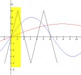
this picture can show where is my question on.
red line: signal 1
blue line: signal 2
black line: triangle wave for compare.
so, what will be happen on the part of the red line in the yellow area?
will this signal be lost?
Attachments
Hi,
Is not lost because the red modulates the blue one. (Really do not see two separate signals) but a modulated signal on the other. This affects the result of the comparator.
Is not lost because the red modulates the blue one. (Really do not see two separate signals) but a modulated signal on the other. This affects the result of the comparator.
Last edited:
It is a little dangerous to say one input signal modulates the other one. The term modulation is normally used when one signal is used to influence the other (like control its amplitude, phase or frequency).
The "payload" that is going to the modulator is actually the SUM of both input signals (which in this case haere would be high enough to overmodulate BTW). This is also called linear superposition.
There is however some modulation (i.e. mutual influence like IMD) going on in practice due to circuit non-idealities, but this is a separate chapter.
Regards
Charles
this picture can show where is my question on.
red line: signal 1
blue line: signal 2
black line: triangle wave for compare.
so, what will be happen on the part of the red line in the yellow area?
will this signal be lost?
You can't expect such a small fraction of the signal to pass through individually on a sampled system! Your question basically refers to the sampling theory, however in this case the sampling intervals are not uniform. Between two sampling points the datails of the original signal are "lost", but if it was appropriately band-limited, these points can be restored (by a filter) from the other time-points. In case of uniform sampling the bandwidth should be less then half as the sampling frequency to achieve perfect restoration (Shannon-theorem), in case of PWM ("natural sampling"), the restoration always have some error, the higher the fsw/fsignal ratio, the lower the error.
An other question is signal level: the sum of the signals should not exceed the triangle amplitude.
If signal amplitude is OK, and freq of every components are lower then 1/5th...1/20th of the triangle, then the original signal can be restored, but you won't see it in a small time window. (1/5: acceptable, 1/20: almost perfect)
One more thing: one modulating signal (wich can be the sum of two sine wave) goes into the modulator, one PWM signal comes out, and one signal can be restored, the original sine waves cannot be seprated (unless the receiving side knows what was transmitted).
Summary: PWM is approximately a quasy-linear operation, if we assure the neccessary conditions.
Last edited:
Hi,It is a little dangerous to say one input signal modulates the other one. The term modulation is normally used when one signal is used to influence the other (like control its amplitude, phase or frequency).
The "payload" that is going to the modulator is actually the SUM of both input signals (which in this case haere would be high enough to overmodulate BTW). This is also called linear superposition.
There is however some modulation (i.e. mutual influence like IMD) going on in practice due to circuit non-idealities, but this is a separate chapter.
Regards
Charles
I answered the question: "lose red signal?"
do not lose anything. is a different matter if the effect of the modulator (comparator with a triangular signal on pin) in this case, the PWM output will have both the segnali.eg: the pulse width modulation will have 100Hz and at the same time will change width of pulse to frequency of the second signal eg. 20Hz).
Of course there are the proportions for the two signals. amplitude and time domain.
Also,addition or subtraction produces the same result for intermodulation.
Difference is only in reference to a third signal.
Hi,
I answered the question: "lose red signal?"
do not lose anything. is a different matter if the effect of the modulator (comparator with a triangular signal on pin) in this case, the PWM output will have both the segnali.eg: the pulse width modulation will have 100Hz and at the same time will change width of pulse to frequency of the second signal eg. 20Hz).
Of course there are the proportions for the two signals. amplitude and time domain.
Also,addition or subtraction produces the same result for intermodulation.
Difference is only in reference to a third signal.
I agree with you, "the PWM output will have both the signal", although i unable to do some testing to verify, logically, it can be.
but, the another issue is the FET in class-d amp normally working at the switch status, how can FET differentiate those 2 PWM.
and also, the LPF behind the FET, how can it works.
thanks
Hi,
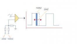
Sorry for very simple pic .
Concept is clare, in this case two modulation is present at output di class D amplifier (100hZ & 20hZ).
My previous post refers to the same concept but using
high frequencies (near to carrier). to obtain the fix of the band and at the same time neutralize the artifacts of the conversion. This is the new concept on which the modulator MXD. is totally new and a bit complex to manage the phase signal (this changes with the modulation).
Someone on the thread "DXA-400 amplifier" said I probably copied ....😛
Just measure the pin of the comparator to see that there are two signals at carrier frequency.🙂
Regards
Attachments
JJwzhao!
Have you heard about fourier transformation, transfer function, and bode plot? The behaviour of a filter can be described this way.
Or can be simulated. Why don't you download a simulator program?
There are no 2 PWMs, only one!
Do you understand how does PWM work with one signal? Then you should have understood how it works with a composite signal. Don't mess with two high freq signals! Think it over at DC signal! Next step: a sinewave (or any wave!) can be approximated by the series of short DC signals, so if the DC goes through the system, then any signal does (as long as it is slow enough.)
Have you heard about fourier transformation, transfer function, and bode plot? The behaviour of a filter can be described this way.
Or can be simulated. Why don't you download a simulator program?
how can FET differentiate those 2 PWM.
There are no 2 PWMs, only one!
Do you understand how does PWM work with one signal? Then you should have understood how it works with a composite signal. Don't mess with two high freq signals! Think it over at DC signal! Next step: a sinewave (or any wave!) can be approximated by the series of short DC signals, so if the DC goes through the system, then any signal does (as long as it is slow enough.)
Hi,
To Pafi.
I have simple curiosity, Think You are advanced,then sorry for very stupid question.
what is result (frequency & signal morfology) at output?
Regards
To Pafi.
I have simple curiosity, Think You are advanced,then sorry for very stupid question.
what is result (frequency & signal morfology) at output?
Regards
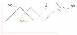
Is that triangle a comparator?
300 kHz square, duty cycle is 40 or 60% depending on the input polarity. Is this a real question? (I don't think so.)
300 kHz square, duty cycle is 40 or 60% depending on the input polarity. Is this a real question? (I don't think so.)
Last edited:
Is that triangle a comparator?
300 kHz square, duty cycle is 40 or 60% depending on the input polarity. Is this a real question? (I don't think so.)
Hi,
I had no real doubting that you respond appropriately.
Now imagine that a phase change (increase / decrease) from 180 °.
two signals are the same high frequency, but the result (PWM mode) will contain the audio information (audio frequency).
Do you agree on this?
Then is possible apply two high frequency signals.
Sorry, I was wrong, the duty cycle is 50 %, independently from the phase shift.
I don't know where does this "audio information" comes from. You haven't mentioned anything about any audio signal before.
I don't know what do you write about.
two signals are the same high frequency, but the result (PWM mode) will contain the audio information (audio frequency).
Do you agree on this?
I don't know where does this "audio information" comes from. You haven't mentioned anything about any audio signal before.
Then is possible apply two high frequency signals.
I don't know what do you write about.
JJwzhao!
Have you heard about fourier transformation, transfer function, and bode plot? The behaviour of a filter can be described this way.
Or can be simulated. Why don't you download a simulator program?
There are no 2 PWMs, only one!
Do you understand how does PWM work with one signal? Then you should have understood how it works with a composite signal. Don't mess with two high freq signals! Think it over at DC signal! Next step: a sinewave (or any wave!) can be approximated by the series of short DC signals, so if the DC goes through the system, then any signal does (as long as it is slow enough.)
Hi, Pafi
I think you may not understand my question, and your thought is already far away my question, think you are advanced.
i know no 2 PWMs, i mean the result of the comparator with 2 signals and the 1 triangle.
BTW, which software can do simulation, i'm not the one specially do circuit designing, i'd like to learn now.
thanks
Hi,
Sorry for very simple pic .
Concept is clare, in this case two modulation is present at output di class D amplifier (100hZ & 20hZ).
My previous post refers to the same concept but using
high frequencies (near to carrier). to obtain the fix of the band and at the same time neutralize the artifacts of the conversion. This is the new concept on which the modulator MXD. is totally new and a bit complex to manage the phase signal (this changes with the modulation).
Someone on the thread "DXA-400 amplifier" said I probably copied ....😛
Just measure the pin of the comparator to see that there are two signals at carrier frequency.🙂
Regards
Dear Ap2,
on the square wave, it looks it delay the comparision for 20Hz signal, or ......?
still not understand it.
thanks
...
BTW, which software can do simulation, i'm not the one specially do circuit designing, i'd like to learn now.
...
Hello JJwzhao,
Ltspice is a good choice.
Linear Technology - LTspice IV Downloads and Updates
Cheers,
- Status
- Not open for further replies.
- Home
- Amplifiers
- Class D
- possibility of signal lossing