New start:
- relay volume control at the input (micro with touch LCD),
- 6112 with CCS for the voltage amplifier (enough voltage for up to 300 ohm headphones),
- BUF634 or class A operationel amplifier (enough current for down to 16 ohm headphones),
- or Sowter 8650 output line transformer (needs to talk with Sowter for a smaller version),
- LiFePO4 battery powered with BMS.
Perhaps Rob Colemanns adapted DHT heather supply?
What do you think about the idea?
Take a look at (and the prices!):
V-MODA VAMP VERZA (its not tube powered)
The Continental Headphone Amplifier | ALO Audio
Done already - would settle for a fraction of those prices 😉
http://www.diyaudio.com/forums/tube...amp-all-tube-direct-heated-portable-fits.html
http://www.diyaudio.com/forums/tube...amp-all-tube-direct-heated-portable-fits.html
Sowter says: "Designed to be driven from a cathode follower output stage via a coupling capacitor..."
Have you calculated that 3 mA thru a CCS is enough to drive the transformer/phones ?
Have you calculated that 3 mA thru a CCS is enough to drive the transformer/phones ?
I read a lot of internet papers about Parafeed, but I am a beginner with this topologie!
What does the OPT needs? No current (capacitor coupled) but only the right voltage swing? (5k primary impedance and 53,7Vrms)
The 3mA CCS is for the tube only. +210VDC for a voltage swing of 150Vpp for 2Vpp input.
Re: Sowter 8665 transformer. - VoltSecond - Bottlehead Forum
What does the OPT needs? No current (capacitor coupled) but only the right voltage swing? (5k primary impedance and 53,7Vrms)
The 3mA CCS is for the tube only. +210VDC for a voltage swing of 150Vpp for 2Vpp input.
Re: Sowter 8665 transformer. - VoltSecond - Bottlehead Forum
In your case the OPT Sowter 8665 is designed to be used with cathode follower, which has low output impedance. Your circuit is an ordinary common cathode circuit, which has relatively high output impedance. Therefore it is likely that the frequency response - with your circuit - is highly limited at the bass end. Sowter does not specify the primary inductance of 8665, unfortunately. Knowing this would clarify this situation a lot.
You do not need 150 Vpp voltage swing in a primary of a headphone amplifier, but I think you need more current than 3 mA to have 6111 working linearly.
You do not need 150 Vpp voltage swing in a primary of a headphone amplifier, but I think you need more current than 3 mA to have 6111 working linearly.
Your suggestions?
The OPT has a primary of 4.4K.
I need a small miniature tube for a portable device. What can I use for tube and what should be the supplied current?
The OPT has a primary of 4.4K.
I need a small miniature tube for a portable device. What can I use for tube and what should be the supplied current?
...The OPT has a primary of 4.4K.
I need a small miniature tube for a portable device. What can I use for tube and what should be the supplied current?
Output transformer does not have any specific output impedance, such as 4k4.
It has some turns ratios and the impedance it reflects to primary depends on the load at secondary and turns ratio.
I suspect that the inductance of the primary is too low to be used with any common cathode connected small signal triode.
You should use one side of 6111 as a voltage amplifier and the second half as a cathode follower.
- Posted by VoltSecond (A) on August 2, 2001 at 21:03:17 In Reply to: Sowter transformer. posted by G on August 2, 2001 at 20:01:08:
12:1
6:1 and
4:1**************
I read the spec to say output voltage rating to be 0.5W at the 40 ohms (12:1) setting which coverts to be 4.47V RMS. This will be 53.7 V RMS on the primary.
At the 6:1 setting the output voltage rating will be 8.94 V RMS with 53.7 V on the primary.
At the 4:1 setting the output voltage rating will be 13.4 V RMS with 53.7 V on the primary.
********************
With a 4.4K R_plate and the 4:1 setting, the tube provides an output impedance of
4.4K/(4:1)^2 = 4.4K/16 = 275 ohms + the DCR of the secondary + the DCR of the primary/turns ratio squared.
275 + 36 ohms + about 36 ohms = 347 ohms.
*******************
With a 4.4K R_plate and the 6:1 setting, the tube provides an output impedance of
4.4K/(6:1)^2 = 4.4K/36 = 122 ohms + the DCR of the secondary + the DCR of the primary/turns ratio squared.
122 + 18 ohms + about 16 ohms = 156 ohms.
*******************
With a 4.4K R_plate and the 12:1 setting, the tube provides an output impedance of
4.4K/(12:1)^2 = 4.4K/144 = 30.6 ohms + the DCR of the secondary + the DCR of the primary/turns ratio squared.
30.6 + 4 ohms + about 4 ohms = 38.6 ohms.
***************
Note: Usually the reflected DCR of the primary for a "two winding" transformer equals the DCR of the secondary.
... and the the espressivo is an anode follower parafeed into the 5k Peerless TL-404!
With a 4.4K R_plate and the 4:1 setting, the tube provides an output impedance of 4.4K/(4:1)^2 = 4.4K/16 = 275 ohms + the DCR of the secondary + the DCR of the primary/turns ratio squared.
275 + 36 ohms + about 36 ohms = 347 ohms.
This is wrong way to deal with the transformers.
The tube do not provide any impedance to the output, contrary, the load at the output "provides" certain impedance to the tube.
Do you have any idea what power or voltage level is required for typical headphones ?
300R: 200mW@22Vpp@26mA (HD800)
20R: 200mW@5.8Vpp@100mA (Ultrasone IQ)
No problem for high impedance headphones. But the low impedance headphones needs current!
If OPT´s safe the wattage and if the cathode follower supplies without problems high impedance headphones through capacitor and OPT (5k to 300R winding), then why itsn´t possible to drive low impedance headphones (5k to 30R winding) refered to Sowter 8665 OPT?
300R: 200mW@22Vpp@26mA (HD800)
20R: 200mW@5.8Vpp@100mA (Ultrasone IQ)
I listen with 32 ohms headphones from my laptop. Its max. output level is some 1 Vrms (= 30 mW) and the sound level is sufficient.
Is 200 mW really necessary ?
With cathode a follower or similar low output impedance output stage and Sowter 8665 there is no problem.
But with a single 6111 having 3 mA current, no way.
Aquavite - Headphone amp
Hi guys,
sorry to enter this thread so late, but I was alerted by the DIY-Audio system yesterday. I am the designer of the mentioned "AQUAVITE" and JPS1964 asked me about this topic via private eMail from my website. After having read this thread, I believe there are some misunderstandings, that should be cleared.
@ artosalo: You are absolutely right - the TX does not provide a sudden impedance to the tube by itself, but it transforms the impedance of the load to the tube. For example - if the mentioned ratio of 12:1 is used, a 50ohm capsule will show as (12^2 * 50ohm) or 7200 ohm at the primary.
@ jps1964: You asked me about using my design for this purpose and I told you, that I think it will not have sufficient output voltage for driving this TX. You should better search for a TX of lower ratio.
Solving the riddle: A cathode follower, driven by a JFET in hard-coupled mode will give app. 3 - 4Vrms at the output. Because this design was made to drive sophisticated dynamic 600ohm capsules this is more than enough. Such a 600 ohm headphone will show app. 110dB SPL @ 1mW input. Because we speak about a 600ohm device, this will be 0,775Vrms.
Connecting a low impedance capsule will change things, although the SPL will not really change with input power (@ artosalo -> right!). BTW - if other type of capsules (e.g. no dynamic ones) are used, this will not be true, because they normally show less efficiency. Sounding abilities should be estimated as "the better the efficiency, the better the performance".
One more example: Using a 50 ohm dynamic capsule will again show app. the same SPL at the power level, but in this case the according voltage will be 223mV and the input current will be 4,5mA. Giving this arrangement the same headroom like before, we need 5x the voltage/current values, which in fact will settle to 25x the power.
Searching for a proper TX we find, that a ratio of app. 3:1 will be optimum since 0,775V / 0,223V -> app. 3x.
Coming to the tubes idling current: We see, that we need 1/3x the load's current to be supplied by the cathode follower. In our case this is 5*4,5mA / 3 = 7,5mA max. Here you can see, that it is no tedious task for the little 6C31B. For real, the idling current has to be app. 1,41 times bigger than the primary current, because we had to deal with peak values instead of rms. So we set the idling current to 1,41 * 7,5mA * 2 (for to sleep better!!) = 21mADC. The quiescent power dissipated by the triode is therefore (68V - 15V) * 21mA = 1,11W. Smaller than 50% of max. power.
In my design I set the idling current to app. 15mA, so the cathode resistor of the 6C31B had to be changed to app. 6k8 in this case.
Considering 3,5Vrms at the output of the cathode follower will give app. 3,5V/3 = 1,17Vrms at the capsule, which in fact will lead to app. 124dB SPL to your ears. Good luck for your hearing!
I hope you will be able to determine other ratios for other capsule impedances if you follow my simple cooking recipe. If you need more information, pls. do not hesitate to ask!
Best regards from Linz/Austria,
Barbara E. Gerhold
http://www.tubeclinic.com
Aquavite
Hi guys,
sorry - I found a typing error in my posting:
To set the idling current to 21mA instead of 15mA will need a cathode resistor value of 680 ohm instead of 1k originally.
A value of 6k8 (like I wrote in my posting) will give 2,1mA ... my fault, sorry again!
BR, Barbara
Hi guys,
sorry - I found a typing error in my posting:
To set the idling current to 21mA instead of 15mA will need a cathode resistor value of 680 ohm instead of 1k originally.
A value of 6k8 (like I wrote in my posting) will give 2,1mA ... my fault, sorry again!
BR, Barbara
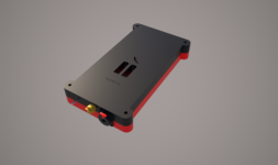
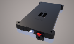
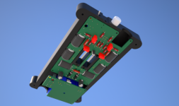
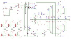
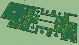
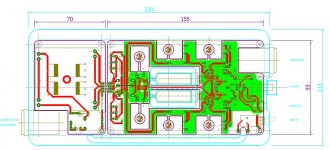
Here for comments!
Click the image to open in full size.

Alas, the image does not show, and clicking the link gives the error "414 - The requested URL's length exceeds the capacity limit for this server."

- Status
- Not open for further replies.
- Home
- Amplifiers
- Tubes / Valves
- Portable tube amplifier