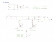
Suppose you own the following Parametric EQ circuit (I don't  ). It was designed for electric instruments, but you want to use it with a low impedance (line level) source.
3-band parametriq EQ (slim) - PCB
3-band parametriq EQ (slim) – PCB – TH custom effects
Would it suffice replacing the 1M input resistor and 1M pots for, say, 10k values, to have it 'properly' working? Or the whole chain of caps/resistor values (or even opamps) would have to be revised? Or, for instance, additional parts to be added?
Personally, I need a portable PEQ for experimenting with on-the-fly recordings..., Q control is very important for me. However, the closest I've found (analog and portable) are designs for guitars or high imp. instruments. Their size and 9v battery power supply are convenient, but I need low impedance to plug it to the line out of any mic preamp.
If this works, I thought it could be also interesting to use as a small PEQ stage between my DAC and active speakers. This might sound like non-sense or simplistic, but that simple is my knowledge here and I'm curious about what experienced listeners think about it. I have never used an analog PEQ before indeed, only digital filters.
If there are also any comments on the quality of the circuit itself, please let me know. Maybe the whole experiment would turn out in disappointment because of noise/phase shift or bandwidth control the design offers.
Thanks!
Domingo
). It was designed for electric instruments, but you want to use it with a low impedance (line level) source. 3-band parametriq EQ (slim) - PCB
3-band parametriq EQ (slim) – PCB – TH custom effects
Would it suffice replacing the 1M input resistor and 1M pots for, say, 10k values, to have it 'properly' working? Or the whole chain of caps/resistor values (or even opamps) would have to be revised? Or, for instance, additional parts to be added?
Personally, I need a portable PEQ for experimenting with on-the-fly recordings..., Q control is very important for me. However, the closest I've found (analog and portable) are designs for guitars or high imp. instruments. Their size and 9v battery power supply are convenient, but I need low impedance to plug it to the line out of any mic preamp.
If this works, I thought it could be also interesting to use as a small PEQ stage between my DAC and active speakers. This might sound like non-sense or simplistic, but that simple is my knowledge here and I'm curious about what experienced listeners think about it. I have never used an analog PEQ before indeed, only digital filters.
If there are also any comments on the quality of the circuit itself, please let me know. Maybe the whole experiment would turn out in disappointment because of noise/phase shift or bandwidth control the design offers.
Thanks!
Domingo
Attachments
If you scale the resistors down you have to scale the capacitors up the same factor to keep the frequencies the same.Would it suffice replacing the 1M input resistor and 1M pots for, say, 10k values, to have it 'properly' working? Or the whole chain of caps/resistor values (or even opamps) would have to be revised? Or, for instance, additional parts to be added?
There are several places in the signal path with 10k series resistors - scaling thosedown to 1k will reduce noise somewhat and may be worth doing, ditto for the 33k feedback network on the output opamp. Larger resistor values have more voltage noise.
Would it suffice replacing the 1M input resistor and 1M pots for, say, 10k values, to have it 'properly' working? Or the whole chain of caps/resistor values (or even opamps) would have to be revised? Or, for instance, additional parts to be added?
Basically, you should do... nothing at all. It has a high impedance input, so if you plug it into a low impedance source, it'll work just fine (it's the other way around, Hi-Z instrument on line input that doesn't work). The first opamp on the left buffers the source, what happens after that no longer depends on source impedance.
So, just build it 😀
Impedances used inside the circuit matter only for noise. If, you find it too noisy for your tastes, then you can reduce resistor values, but as Mark says, since you need to scale up the capacitors in proportion, they're going to be huge.
TL072 has a non cascoded FET input stage so it has quite a bit of distortion caused by input FET Cgd variation with input voltage. This causes a nonlinear gate (input) current, so it increases with source impedance. In other words, you can remove R1.
Now you can decrease R6 R7 as Mark says but TL072 has a super wimpy output stage which considers a 2 kOhm load "heavy" so don't overdo it.
If you want lower noise and use it on a line output, a simpler solution would be to rewire the input buffer into an amplifier with gain 2, and rewire the output amp (IC3B) with gain 1. So you get the same amount of noise but the signal going through the circuit is 2x larger, so you get better SNR. That's only possible if the voltage swing doesn't make the opamps clip, of course.
You could also consider more modern FET opamps like OPA1642 or OPA1652.
Last edited:
Thank you guys for your replies!
I feel immediately encouraged and already started listing up the parts I need.
I never worked with OPs before, but I've been wanting to. What would be the most important parameters to look at here? There are many options in the local provider. OPA1642 one of them but not for DIP-8 socket. I would be generous there, even though I have to get everything twice to make it stereo (my plan is to use low tolerance dual pots and two boards in parallel).
I will remove R1 and reduce R6 and R7, as advised.
Should I lower the value of R2 also? 1M seems insufficiently high, but if it affects the whole circuit I would leave it as it is.
What Mark points out there applies to all resistances in the circuit? Or only to the ones within each band filter? ie. R5 and R8 in the Low Band filter. And what about the 1M variable resistors (pots) to control frequency? Would it be advisable to lower their value as well? Or that would again mean a necessary increase of caps. Sorry for my ignorance.
I don't know how to do that rewiring @peufeu, I will reflect on it.
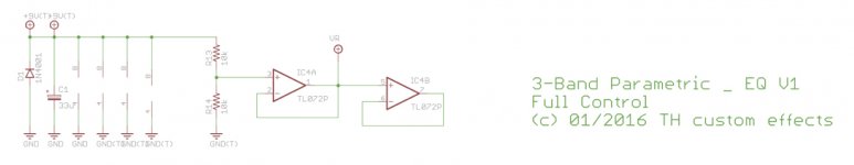
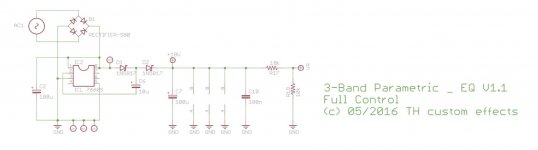
BTW, the designer offers an updated version of the circuit which doubles power "for more headroom and less distortion", but using the same single 9v battery. The PCB is quite bigger which I dislike for casing and making it stereo, but it takes on a different approach and I wonder about your opinion about it. Is that upgrade worthy for line ("studio") purposes or is it for instance more relevant for highly dynamic instruments? In attachment you can see the two power supply sections which I'm talking about compared, if they are of any interest (v1 and v1.1).
Thanks again for your help! I hope to not overwhelm anybody with so many questions in my head.
Domingo
I feel immediately encouraged and already started listing up the parts I need.
I never worked with OPs before, but I've been wanting to. What would be the most important parameters to look at here? There are many options in the local provider. OPA1642 one of them but not for DIP-8 socket. I would be generous there, even though I have to get everything twice to make it stereo (my plan is to use low tolerance dual pots and two boards in parallel).
I will remove R1 and reduce R6 and R7, as advised.
Should I lower the value of R2 also? 1M seems insufficiently high, but if it affects the whole circuit I would leave it as it is.
If you scale the resistors down you have to scale the capacitors up the same factor to keep the frequencies the same.
What Mark points out there applies to all resistances in the circuit? Or only to the ones within each band filter? ie. R5 and R8 in the Low Band filter. And what about the 1M variable resistors (pots) to control frequency? Would it be advisable to lower their value as well? Or that would again mean a necessary increase of caps. Sorry for my ignorance.
If you want lower noise and use it on a line output, a simpler solution would be to rewire the input buffer into an amplifier with gain 2, and rewire the output amp (IC3B) with gain 1.
I don't know how to do that rewiring @peufeu, I will reflect on it.
BTW, the designer offers an updated version of the circuit which doubles power "for more headroom and less distortion", but using the same single 9v battery. The PCB is quite bigger which I dislike for casing and making it stereo, but it takes on a different approach and I wonder about your opinion about it. Is that upgrade worthy for line ("studio") purposes or is it for instance more relevant for highly dynamic instruments? In attachment you can see the two power supply sections which I'm talking about compared, if they are of any interest (v1 and v1.1).
Thanks again for your help!
I hope to not overwhelm anybody with so many questions in my head.Domingo
Attachments
Last edited:
R2's purpose in life is just to ensure the input side of C2 is discharged to 0V. If it was charged to a random voltage, when you plug in a connector, which presumably has 0V signal on it, whatever voltage on C2 would be added to the signal until it discharges through R4, resulting in a huge loud pop in the speakers. So the value of R2 is not critical at all, and it won't add noise, because when you plug in the source, it is across the low impedance line source output.
> What would be the most important parameters to look at here?
With the large resistors you need opamps with low input current (offset voltage = input resistance * input current) and also low input noise current. This means FET or JFET input opamps, not bipolar transistor input.
> What Mark points out there applies to all resistances in the circuit?
All the resistors that make a filter with a nearby cap.
> And what about the 1M variable resistors (pots) to control frequency?
Yes they combine with the cap on the other side of the "+" input of the opamp, so if you put a 100k pot you'd have to divide R8 by 10 and multiply C5 by 10, etc.
> BTW, the designer offers an updated version of the circuit which doubles power "for more headroom and less distortion", but using the same single 9v battery. The PCB is quite bigger which I dislike for casing
Well you said you wanted to alter the Q, the first version has tiny trimmer pots for that so you need a screwdriver, the bigger version has knobs which should be vastly more usable, but of course bigger. So... you decide if you want knobs or not.
As for "2x more powaaarrrr" well, it uses a voltage inverter chip to make a negative supply so it can process double the voltage.
What's the output voltage of your source?
btw, you say you want it small and you don't like SMD opamps?
In my long experience: most folks who think they want a parametric, never figure out how to use it.
If you are a novice, do NOT try to re-design one before you try one. I don't see anything much wrong with the designs linked here, *for the price and complexity*. You already showed the you don't see past the 1Meg at the input to the 100K after the cap, and modern audio is NOT impedance-matched so it does not matter. The TL07x opamp IS the go-to for many-many semi-pro and even pro units. It is not best at anything but is calm and easy to work with. While sockets are a long-term maintenance headache (I once had a job pressing my thumb on every chip in a flock of Apple ][ computers), your beginner prototype sure can be socketed to try other chips.
This is a SIMPLE "parametric". It is not constant Q; the Q changes with frequency. The fix for this is 2 to 8 more opamps per band. Try to find the old RANE papers and service manuals for the "correct" way to do parametric.
And..... IMHO, it is foolish to build a para. Go to the Used Rock Music Gear Shop and buy a beat one. You can rarely build stuff like this for the new/list price (mass production economy), and used gear trades for 2/3rd to 1/4 of new price. Another part of my life revolved around a $1500 TASCAM mixer I bought for $200. (OK, that was partly because it was in a fire and it took 5 years for the smoke-smell to dissipate from the Asian woodwork.)
Last edited:
Unfortunately what I need doesn't exist in the market, neither vintage, as far as I know. Otherwise I would be the first buyer.
I mean a portable PEQ of at least 3-bands to tweak field recordings on the fly. I make sound for docs and experimental films so I use software PEQs on a daily basis, but I need to port this to the streets. Simple: If I hear birds I can in realtime emphasise those freqs and leave the rest, rather than doing it in post. This is for creative purposes, too rare for the industry and field recorders unfortunately only include low pass filters. Some high pro-line recorders are now having 3-band PEQ but not affordable to me (ie. Roland R-44).
One way would be to implement it with micro-controllers and DSP. For example a Teensy ARM with Audio Board etc., but transparency might suffer and I suspect analog would give more harmonic-less noticeable results. Recently I built a transistor based headphones amp (JLH) and was so fascinated by the transparency of it that I thought why not try to implement this PEQ-microphone analog too. That a guitar effect might work is already great news 🙂
Ideally a very simple and clean 9v preamp circuit or PCB for electret capsules. If you have any recommendations that would fit please be my guest. At the moment I intend to use a JuicedLink DS214 not in production anymore. I'm very dear to it, love its old school clarity and simplicity, but noisy as hell almost unbearable (I see a TL074 inside, maybe that explains something).
That's a bummer and good to know. How does that work in practice? Can you compensate manually the changes in Q as you change frequency, by turning both pots simultaneously and some practice? Compensating/correcting is no problem for me, but ideally I would need capacity to control over Q4.5 across the whole range of each band.
Also, how does band gain work in this circuit? I'm used to digital PEQs where when the pot is centred gain is 0dB, moving it to the sides brings band gain up or down. Does this analog design work the same way (for which I would ideally need balance pots with centre detent)?
Thanks for the explanations. Maybe this topic should be renamed to "Portable Analog PEQ" since the issue of impedance has been already ruled out. Should it be moved to the instruments section, please let me know as well.
I mean a portable PEQ of at least 3-bands to tweak field recordings on the fly. I make sound for docs and experimental films so I use software PEQs on a daily basis, but I need to port this to the streets. Simple: If I hear birds I can in realtime emphasise those freqs and leave the rest, rather than doing it in post. This is for creative purposes, too rare for the industry and field recorders unfortunately only include low pass filters. Some high pro-line recorders are now having 3-band PEQ but not affordable to me (ie. Roland R-44).
One way would be to implement it with micro-controllers and DSP. For example a Teensy ARM with Audio Board etc., but transparency might suffer and I suspect analog would give more harmonic-less noticeable results. Recently I built a transistor based headphones amp (JLH) and was so fascinated by the transparency of it that I thought why not try to implement this PEQ-microphone analog too. That a guitar effect might work is already great news 🙂
@peufeu: What's the output voltage of your source?
Ideally a very simple and clean 9v preamp circuit or PCB for electret capsules. If you have any recommendations that would fit please be my guest. At the moment I intend to use a JuicedLink DS214 not in production anymore. I'm very dear to it, love its old school clarity and simplicity, but noisy as hell almost unbearable (I see a TL074 inside, maybe that explains something).
@PRR: This is a SIMPLE "parametric". It is not constant Q; the Q changes with frequency.
That's a bummer and good to know. How does that work in practice? Can you compensate manually the changes in Q as you change frequency, by turning both pots simultaneously and some practice? Compensating/correcting is no problem for me, but ideally I would need capacity to control over Q4.5 across the whole range of each band.
Also, how does band gain work in this circuit? I'm used to digital PEQs where when the pot is centred gain is 0dB, moving it to the sides brings band gain up or down. Does this analog design work the same way (for which I would ideally need balance pots with centre detent)?
Thanks for the explanations. Maybe this topic should be renamed to "Portable Analog PEQ" since the issue of impedance has been already ruled out. Should it be moved to the instruments section, please let me know as well.
- Home
- Source & Line
- Analog Line Level
- Portable Analog PEQ - High to Low impedance conversion