For the TC9? If you have figured out how to take a driver with 0.9 Qt out of the box and have a Q of 0.6 in the box, the current amp guys want to talk to you.
dave
Here is the measured Qts for the TC9FD in free-air (Qts=0.922) and in the 1.1 liter Dagger (Qts=0.724). That is a substantial flattening of the impedance peak by the sealed aperiodic TL to do that.

Attachments
Thanks for the input everyone! I may just seal these up, stuff and listen. Regardless of the driver used (any of the three inchers I have in my collection) they will be used with sub.
Zilla
Zilla
I'd like to see a Qtc with the TC9FD. Running the 10F through WinIDS in a 1.1l sealed box gives a Qtc of 0.636.
Hmmmmmm.
Bob
X can you confirm this that when talks Dagger combined 10F its the the sealed Dagger see below and when talks Dagger combined TC9FD its the Dagger that is open in the end (TL) see below and makes a difference : )Here is the measured Qts for the TC9FD in free-air (Qts=0.922) and in the 1.1 liter Dagger (Qts=0.724). That is a substantial flattening of the impedance peak by the sealed aperiodic TL to do that.
10F in sealed Dagger.
TC9FD in Dagger (TL).
Last edited:
Thanks for the input everyone! I may just seal these up, stuff and listen. Regardless of the driver used (any of the three inchers I have in my collection) they will be used with sub.
Zilla
Think xrk971 Dagger (TL) seems a very promising box for TC9FD, here link to some very good sounding sound clips from that box http://www.diyaudio.com/forums/full-range/268037-fast-tl-8.html#post4192688.
X can you confirm this that when talks Dagger combined 10F its the the sealed Dagger see below and when talks Dagger combined TC9FD its the Dagger that is open in the end (TL) see below and makes a difference : )
10F in sealed Dagger.
TC9FD in Dagger (TL).
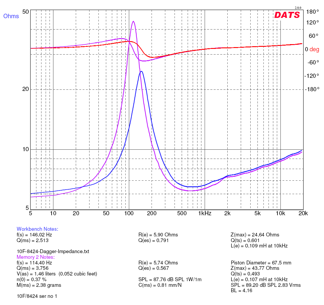
The DATS plots above are from the same sealed Dagger that the 10F ref monitor uses. It is different than the open ended Dagger but I can't recall off hand what the difference is.
For comparison here is the 10F/8424 in the same Dagger:
Last edited:
xrk971,
Thanks verifying looks like Dagger is very good compared ordinary squarer boxes thanks sharing it with us.
Thanks verifying looks like Dagger is very good compared ordinary squarer boxes thanks sharing it with us.
xrk971,
Thanks verifying looks like Dagger is very good compared ordinary squarer boxes thanks sharing it with us.
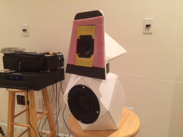
You are welcome. The Dagger, is very compact, doesn't require a lot of volume to shed the boxy sound. There is no coloration, it is very neutral.
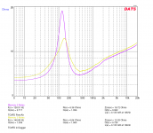
I just put the TC9FD in the vented Dagger TL (green) and the Qts is higher than the sealed (yellow)- although the dimensions of the Dagger are not identical. Free air is magenta color:
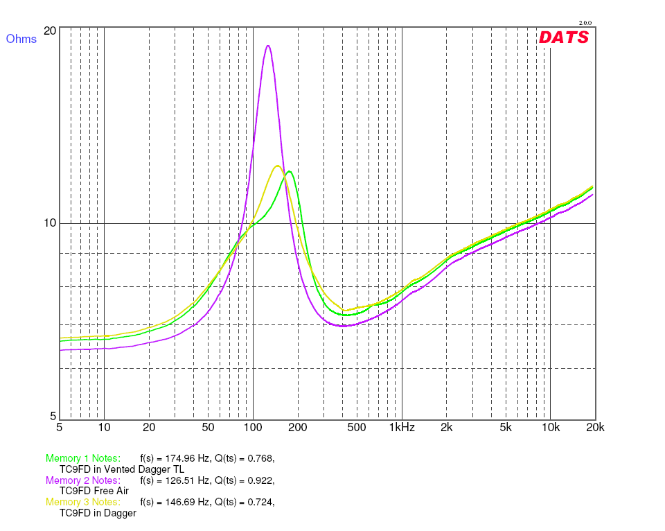
There is a small feature in the peak that makes it asymmetric once the vent is added. I recall that the phase is smoother with vent though, and that may be result of the smoother curved shoulders of the peak as evidenced for example near 400hz for sealed vs vented TL.
Attachments

Last edited:
Your Dagger is running as an aperiodic enclosure. No question here. The point of departure is Qtc. The TC9FD has a Qts of ~0.9. The physics of the matter is that ANY enclosure will RAISE Qtc. So, what you need to explain is how the Dagger DECREASES Qtc.
Bob
Bob
I did not realize I was violating physics here... the measurements are the measurements and I trust the DATS v2 as working properly (verified to measure Qts of known drivers properly compared to manufacturer specs, and it measures L and C of know passive components accurately). What I do know is that the impedance peak is wider than the free air case. It is wider because the high-Q mechanical resonance is squashed with all the non-resonant non-parallel walls and lots of stuffing. So I think the effect is coming through as modification of the Qms, not Qes. Look at the TC9FD's Qms, it went from 2.72 to 1.34 before and after the Dagger. The Qes actually went up a little, but the Qms went down a lot - so no magic here that Qts went down as well.
Last edited:
Bob Brines and xrk971,
Its very interesting what is happening comments for below is welcome.
I just checked some of my saved DATS files and actual my 10F/8424 when reaching a certain level of heavy stuffing shows same theme as X do show for TC9FD in that it get lower measured Qts than the same driver show in free air and Qms decrease heavy.
Above 10F is also in a foam core box (DCR) so is there some clue that point to behavior of foam core as box material.
Also i think of if leaking is some of the answer because looking my old files for A10.2 i see same behavior for my left speaker which have a cracked frame that then can leak. Right speaker have textbook Qts higher than in free air and the one with cracked frame have less Qts than in free air and as xrk971 example then resonance get a little wider than the free air. As the A10.2 can leak thru the cracked frame i think 10F in the foam core DCR box have same possibility in that foam core is not stiff as wood and can flex where driver frame and foam touch each other between the four mounting screws.
Nice to see development here after the split.
I ran impedance sweeps with REW; haven't done this before. Here is TC9FD impedance plots I got with driver sealed in 4" PVC pipe with about 13.5" internal length and stuffed full of Dacron batting and with a second TC9FD driver in free air:

This looks very similar to X's results. The TL approach reduces possible number of reflections; and forces sound to travel through greater depth of damping material while constraining internal volume. An external baffle may then be used for dropping the baffle step frequency as desired.
I ran impedance sweeps with REW; haven't done this before. Here is TC9FD impedance plots I got with driver sealed in 4" PVC pipe with about 13.5" internal length and stuffed full of Dacron batting and with a second TC9FD driver in free air:
This looks very similar to X's results. The TL approach reduces possible number of reflections; and forces sound to travel through greater depth of damping material while constraining internal volume. An external baffle may then be used for dropping the baffle step frequency as desired.
Nice to see development here after the split.
I ran impedance sweeps with REW; haven't done this before. Here is TC9FD impedance plots I got with driver sealed in 4" PVC pipe with about 13.5" internal length and stuffed full of Dacron batting and with a second TC9FD driver in free air:
View attachment 491310
This looks very similar to X's results. The TL approach reduces possible number of reflections; and forces sound to travel through greater depth of damping material while constraining internal volume. An external baffle may then be used for dropping the baffle step frequency as desired.
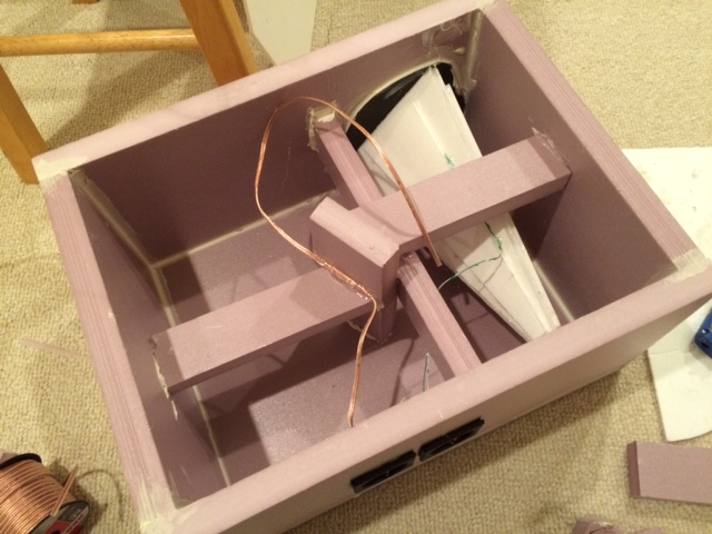
That is interesting that your impedance peak doesn't appear to widen like mine. My TL was about the same length 12in, but perhaps the non-parallel wall shape, small volume, and I used pink fiberglass as the stuffing, and foam core as the walls. The flexing walls may be how I get the wider Qms. This is interesting and can be repeated for identical Dagger with hard material to see if peak stays narrow.
I wonder if the ability of the Dagger to significantly LOWER the Qtc of a high-Q driver, makes it unique? As Bob Brines seems to have not seen any enclosure that can lower Qtc of a driver.
Last edited:
Thanks sharing Barleywater this is interesting.
xrk971 as you notice peak is not wide as yours is in foam core Dagger where peak starts at a lower frq before and ends at a higher frq than the one taken in free air.
For info the leaking A10.2 with cracked frame mentioned post 31 have this same scheme wider than in free air, and that box was made of wood. A10.2 DATS plot below.
Attachments
I wonder if the ability of the Dagger to significantly LOWER the Qtc of a high-Q driver, makes it unique?
No. Just that notmany people measure the Qt of their box.
Here is an impedance curve of FF85k in an aperiodic tapered TL i posted in May 2009.
No Qt looked at, just the flattened impedance curve. This kind of box was 1st pointed out to me at least 30 years ago.
dave
Acoustical impedance increases as sound wave approaches apex; changing impedance causes reflection, thus continuous reflection occurs with decreasing magnitude as wave propagates into taper.
Both X's and Dave's imp plots are as would be expected. Once a leak is introduced into a sealed box, it starts to behave as a ported box. Tiny leak means tiny bump on the imp curve.
I will have to investigate the Qtc thing for myself. I do have the TC9FD on hand, and my first guess as a usable implementation in a FAST speaker is a short stuffed TL, the length of the TL being the depth of the main cabinet -- ~ 11" in my case. I can easily play with stuffing, capping and venting the TL. It may be a couple of weeks, but I will do this.
Bob
Bob Brines,
Any solution that made progress or sound impressions TC9/10F you like to share 🙂.
Any solution that made progress or sound impressions TC9/10F you like to share 🙂.
Last edited:
I have done some rather extensive tests on the TC9FD, 10F and FF85WK.
The TC9FD really needs to be OB or IB. I tested with a 3"dia x 11" pipe that was well stuffed with rockwool. It still showed ripples and reflections. Also, it really needs to be rear mounted. Not a problem, I know how to do it, but still. Rejected.
The FF85WK is smaller than most 3" drivers, has no available excursion and it rated at 5w RMS. It might work as a computer speaker, but it isn't going to keep up with a stout 8" woofer unless crossed very high. Rejected.
I tested the 10F in both IB and a Q=1 sealed box. Works both ways. I need to do some testing in somewhat larger boxes, but whatever that volume is has to come out of main cabinet.
BTW, I have modeled the cabinet for the HM210C0. It will be a 40" tall MLTL. F10 will be around 30Hz.
Bob
The FF85WK is smaller than most 3" drivers, has no available excursion and it rated at 5w RMS. It might work as a computer speaker, but it isn't going to keep up with a stout 8" woofer unless crossed very high.
We don't pay much attention to the excursion & power handling specs. We have used it (FF85wKeN mind you) XOed 1st order at 240 Hz and at about 350 Hz, with quite good results in all 3 cases. No 8"ers thou... 2 & 4 4" Peerless woofers & 2 Silver Flute W14.
dave
- Status
- Not open for further replies.
- Home
- Loudspeakers
- Full Range
- Port Sugestions for 3.5L Enclosure