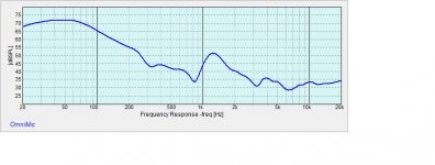
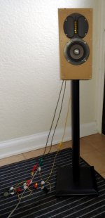
I made a measurement of the ports output today and notice how broad the output is. I thought it would be narrower output. It is 2 MW16P in a 1.5 cu ft vented cabinet 2 inch port 4.5 in long. Am I doing something wrong here. (note this is a flared vent on one side
Attachments
Member
Joined 2003
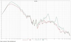
That looks about right to me. Make sure your measurement is set to "all" so that it is not gated, and I would set 1/24oct smoothing to increase resolution.
Apart from the port resonance at 1200Hz and noise floor, the plot should follow what you get in simulated response data.
For quick comparison, I reproduced a model of MW16P that approximates the measurement you have. Port output is the red line, not that different from your measurement I would say.

Apart from the port resonance at 1200Hz and noise floor, the plot should follow what you get in simulated response data.
For quick comparison, I reproduced a model of MW16P that approximates the measurement you have. Port output is the red line, not that different from your measurement I would say.
Yea yours is tuned just a bit lower than mine, looks like 40 hz. I can put back the flare on the other end to lower mine a bit I guess. I thought mine sounded boomy. 50 hz is too high
That's the port's native pipe resonance. The spike frequency is a function of its length.
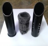
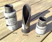
By complete coincidence I completed these measurements today comparing a solid port with a perforated and wrapped damped port. Pile of pictures below. Also attached is the paper by N. B. Roozen of Philips that generated my interest. The responses show the output of the pictured ports measured about 2 cm from the end. The perforated port was measured twice (second not shown) to confirm repeatability and matched nearly perfectly. The responses are smoothed 1/12 octave for better visibility.
By complete coincidence I completed these measurements today comparing a solid port with a perforated and wrapped damped port. Pile of pictures below. Also attached is the paper by N. B. Roozen of Philips that generated my interest. The responses show the output of the pictured ports measured about 2 cm from the end. The perforated port was measured twice (second not shown) to confirm repeatability and matched nearly perfectly. The responses are smoothed 1/12 octave for better visibility.
Attachments
-
 ports.jpg155.8 KB · Views: 294
 -
 12.5 cm port perforation freq.jpg354.3 KB · Views: 285
 -
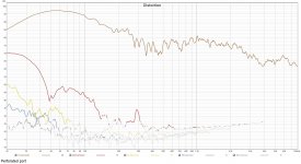
 12.5 cm port perforation solid thd.jpg337.9 KB · Views: 272
 -
 12.5 cm port perforation perf thd.jpg335.4 KB · Views: 254
 -
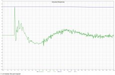
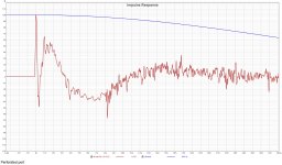 12.5 cm port perforation perf impulse.jpg637.1 KB · Views: 267
 -
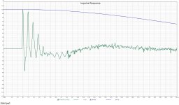 12.5 cm port perforation solid impulse.jpg388.9 KB · Views: 276

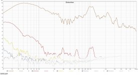
I've been working on some similar ideas here. Very interesting that your HD hasn't quite behaved like mine. 2nd goes down, 4th and 5th up a bit, nothing significant though. In mine all the harmonics went up significantly. Maybe the difference is drive level? I did multiple measurements from 2.38V to 13.52V. This helped find the onset of chuffing. Spectrum plots also helped show that. I'd be curious how yours performs?That's the port's native pipe resonance. The spike frequency is a function of its length.
By complete coincidence I completed these measurements today comparing a solid port with a perforated and wrapped damped port. Pile of pictures below. Also attached is the paper by N. B. Roozen of Philips that generated my interest. The responses show the output of the pictured ports measured about 2 cm from the end. The perforated port was measured twice (second not shown) to confirm repeatability and matched nearly perfectly. The responses are smoothed 1/12 octave for better visibility.
Also what is with the angle cut? Seems like a clever way to keep a pipe resonance from forming if the port isn't really a single length anymore. Was that the intent?
The angle was 45. I suspect the slanted portion is too short to have impact below the highest frequencies. The trials so far are also too casual to derive much definitive beyond that the pipe resonance suppression appears to work well and is worth investigating further.
The test below compared a damped square cut port with a slant cut port. This port is ~ 2 cm shorter than the first but the high frequency harmonics are much lower. The perforations are three sets of spirals to test if the gain loss at resonance peak is caused by the aligned series of perforations creating turbulence. Spirals still show the same ~2 dB peak loss. Should have also mentioned:
The last point means the slant opening directly faces the back of the woofer. It's a test box for a little two way so I may punch holes in different locations to see if performance improves.
The test below compared a damped square cut port with a slant cut port. This port is ~ 2 cm shorter than the first but the high frequency harmonics are much lower. The perforations are three sets of spirals to test if the gain loss at resonance peak is caused by the aligned series of perforations creating turbulence. Spirals still show the same ~2 dB peak loss. Should have also mentioned:
- the ~6 litre cabinet is lined with 1/2" foam carpet pad
- the end of the cabinet furthest from the port is stuffed with acoustic damping
- the port exit is tight to the bottom corner of the cabinet
The last point means the slant opening directly faces the back of the woofer. It's a test box for a little two way so I may punch holes in different locations to see if performance improves.
Attachments

As the port output decreases on the very bottom, wouldn't it be easier to use a closed box instead? Difference between ported and closed box is not too much, and it is presicely here at the port low frequency output. Alright some other advantages as well but also disadvantages like the resonances coming through.
I also did perforated ports some years ago, noticed same thing. Unfortunately, can't seem to find the files now. Had impact on the "mid leakage", didn't have port resonance on my big box small vent. Augerpro has provided lots of data on this lately and thanks for you to doing so as well!
If it is pipe resonance you are seeing, that should have pressure node mid way of the pipe. Try and concentrate your holes there to relieve the pressure. If it is box modes leaking through the port, you could figure out where your pipe end inside the enclosure is. Is it at the pressure node(s) of the box modes like close on some boundary?🙂 I reasoned the box modes vent out through the port if the pressure node happens to be close to the pipe end, and box walls are all about pressure. Try and hit a velocity node of problematic frequency. If still mid leaking, make the port bend and act as low pass filter. I suppose pipe resonance can be triggered by external excitation as well, don't put your port output beside a sound source.
It would be very interesting to hear your thoughts on these additional stuff as well. Have fun experimenting!🙂
ps. in general, the problem is specific to speaker systems that have the bass woofer play mid frequencies as well. As one tries to extend the bass the mids get compromised. Add another way to the system, have separate drivers for bass and mid, and problems can be pushed out of band. I'm not sure why people do 2-way systems and use time and money to get them behave nicely and say 3-way system is complicated and expensive, when it is eventually other way around if measuring by performance.
Last edited:
You're welcome and hard mode challenge accepted. Agree about the benefits of three way but not all domestic environments approve. The speaker in question is the worst case scenario, a vintage Tang Band W4-1320SB and HiVi RT1C-A crossed around 5 kHz and currently living in a scavenged PSB cabinet. The 'woofer' is 3 1/2" with a free air resonance in the 80s while the tweeter easily exceeds 20 kHz flat. A port or passive radiator are the best options for a reasonable balance. I'm actually a bit shocked at the bass now coming from that little cabinet with a bit of wall enforcement.
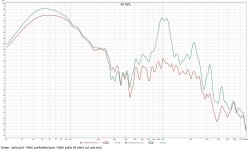
The square end port posted above is perforated along the entire length minus the cabinet wall thickness.The first solid, unperforated port FR displays distinct pipe harmonics to past 6 kHz. Roozen's paper suggested two band of perforations to catch the fundamental and next harmonic but I took the 'nuke it from orbit' approach by perforating the entire length. It seems to work.
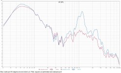
The internal box modes also appear to be separate. The FR below was taken this morning after fully lining the cabinet, replacing 1/2" foam with Ultratouch Denim fixed to the side walls. It reduced both solid and perforated port leakage but had negligible effect on the perforated port's spectral balance. That aligns with Roozen's findings that the spikes are generated by the port itself. If I'm not mistaken he also claims the strong pipe resonance severely degrades the port's bass performance (maybe turbulence?) and that a square cut end may be preferable to a flare.
Again these are all pretty informal results and the port need to be relocated from the rear corner to more properly isolate the effect of the cabinet. The hump between 500 and 3 kHz might still be straight cabinet leakage. I think I'm beginning to understand how Technics achieved such excellent port performance with the SB-C700.
The square end port posted above is perforated along the entire length minus the cabinet wall thickness.The first solid, unperforated port FR displays distinct pipe harmonics to past 6 kHz. Roozen's paper suggested two band of perforations to catch the fundamental and next harmonic but I took the 'nuke it from orbit' approach by perforating the entire length. It seems to work.
The internal box modes also appear to be separate. The FR below was taken this morning after fully lining the cabinet, replacing 1/2" foam with Ultratouch Denim fixed to the side walls. It reduced both solid and perforated port leakage but had negligible effect on the perforated port's spectral balance. That aligns with Roozen's findings that the spikes are generated by the port itself. If I'm not mistaken he also claims the strong pipe resonance severely degrades the port's bass performance (maybe turbulence?) and that a square cut end may be preferable to a flare.
Again these are all pretty informal results and the port need to be relocated from the rear corner to more properly isolate the effect of the cabinet. The hump between 500 and 3 kHz might still be straight cabinet leakage. I think I'm beginning to understand how Technics achieved such excellent port performance with the SB-C700.
Attachments
Since you're in experimental mode, Karlson's original 1/4 WL pipe was kind of a combination of these two, i.e. a slashed pipe end with a tapered 1/2 pipe length slot extension, so experimenting with the taper width/length might garner a new 'critically damped' 1/2 WL vent option.
I read a technique somewhere about putting a sealed T section of a specific length and placement along the port to damp the resonance. Can't recall the detail sorry
FYI/FWIW, here's the exhaust/muffler doc I learned from: https://ntrs.nasa.gov/api/citations/19930092208/downloads/19930092208.pdf
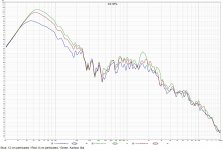
Are details for length, profile shape, etc. available? These tests compare a 14 cm max length, very rough 'Karlson like' port to 12 and 8 cm spiral perforated square cut ports. In this specific application the 'Karlson' appears to behave similar to if slightly better than a shortened square cut port. The primary pipe resonance shifts up significantly in frequency but harmonics are still clearly visible. The resonance appears in the impulse response and is audible near the port as mild 'chuffing' on heavy bass notes...Karlson's original 1/4 WL pipe ....
This port cut was arguably too open to reflect a proper Karlson, explaining the dramatic loss in effective length, but intuitively this should have also improved resonance suppression.
Attachments
Last edited:
- Home
- Loudspeakers
- Multi-Way
- Port Measurement