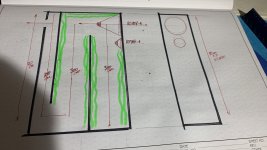
So any suggestion where 2 ports should be placed, along the longest dimension? What about one port?
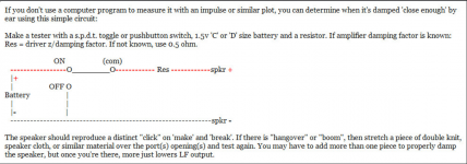
Without measurements, not sure I'm 'buying' this audible far-field cancellation 'bit', but historically, designing a big vent reflex (BVR) tends to have a powerful/peaking vent output/harmonics and critically damping it solves both issues, so recommend one big vent (or more if internal space is an issue) mounted wherever on the back you want and use the click test or impulse response measurement for best accuracy if you're set up for it.
Attachments

Oh yes!
The internal dims in inches are: 15 x 9.25 x 6.75
tuning is 53 hz
please share your thoughts on driver placement and port (one or two) placements
The internal dims in inches are: 15 x 9.25 x 6.75
tuning is 53 hz
please share your thoughts on driver placement and port (one or two) placements
If we were to do some calculations around the 15" dimension, it will give us a worst case scenario because it assumes the driver is in the top or bottom panel of the box, yet it's merely driving from part way along the 15" dimension. For example, if you had the driver and port in the middle of the height, that would effectively cut the box in half and give you a further octave of free space compared to the following...
15" is a quarter wavelength at around 225Hz, which would be the lowest mode. This would reduce in effect moving down to around 1 octave below this, where the box is considered acoustically small, and should be homogenous. This is still 1 octave above the port tuning frequency.
This outlines that you have space on the spectrum to do your transition. You could add stuffing that acts more at 200Hz but less at 50Hz.
Again, dealing with a ~uniform particle density, so locations based on internal dims is moot.Oh yes!
The internal dims in inches are: 15 x 9.25 x 6.75
tuning is 53 hz
please share your thoughts on driver placement and port (one or two) placements
To a degree. I believe there is a good analysis of this topic somewhere which I was reading earlier this year and wish I could put my hands on at the moment.So does this mean that the location of driver and port is not critical?
In any case...
1. Putting the woofer and port in the same end of the cabinet as each other may increase the effect of the length mode (except when they're both in the middle where there is no other end)
2. Calculate the port length resonance to see what will set that off.
3. Use enough damping to manage your mode situation. The idea of only lining a vented box may not always be sufficient, so it's no more than a starting point when you are able to measure.
edit: Guess I should say TTBOMK/IME you're talking about external acoustics, but would like to read what you're referring to.
Regardless, yes, port referenced to the driver can have an impact on vent tuning, so the pioneers originally placed the vent as close as practical to the driver to keep the math simple according to a Bell Labs interview decades later of Albert Thuras, the inventor of the reflex vent.
Regardless, yes, port referenced to the driver can have an impact on vent tuning, so the pioneers originally placed the vent as close as practical to the driver to keep the math simple according to a Bell Labs interview decades later of Albert Thuras, the inventor of the reflex vent.
Last edited:
Are you talking to me? I recall kimmosto was one of the thread contributors if that helps.edit: Guess I should say TTBOMK/IME you're talking about external acoustics, but would like to read what you're referring to.
I know I've known about port positioning for over 20 years so either I analysed it once or simply read about it.
Ok, good to know. I'm not sure that we were talking about the same thing, I was talking about dividing the cabinet dimension.port referenced to the driver can have an impact on vent tuning,
Port or woofer location does not matter too much for the Helmholtz resonance to work because of long wavelength, as long as the path is not blocked and "tuning" is correct. However on a two/three way box where the woofer plays wide bandwidth port resonance or the standing waves inside the box hear out and can be an issue where the port location inside the box will matter. We want the port enabled Helmholtz resonance to boost the lows of the speaker, thats why the port is in the first place. We do not want any midrange noise from the port and ratio of the two marks the success.
Kimmosto had rule of thumb for the mid noise, it is possible to make the mid leaks 15dB below the Helmholz resonance by looking good position for the inlet (for example here in Finnish https://foorumi.hifiharrastajat.org/index.php?threads/pieniä-diy-aiheisia-kysymyksiä.92260/page-99#post-2364006), I would guess this applies to types of speakers where pipe resonance is usually a problem like small two way speakers. Typically measurements posted on forums show mid noise peaks very close to the main resonance making poor performance. Worst I've seen is here https://www.diyaudio.com/community/threads/a-3-way-design-study.376620/post-7190864 where the mid noise is about 6db louder than the low boost making the port ruin the box and new box needs to be built / modified.
What ever you do, if you want to make good performance = iron out obvious issues, make a prototype and measure. If there is issue then move the port, do whatever necessary, until there is no issue.
Stuffing inside the enclosure usually deals with high order modes of the box so they are not a problem leaving few lowest modes possible problem. Put driver mid length and the lowest mode does not happen, then have the port somewhere else than on the boundaries so that the inlet is at null of some of the 2nd / 3rd harmonic to reduce them if they leak out, avoid the pressure nodes of the loudest standing waves. Avoid triggering the pipe resonance if its on the pass band. This might not be practical so put driver and port somewhere else, measure and tweak/rebuild if its a problem. There is always possibility to make a box without any ports, or box whose port pipe resonance and modes is far out pass band = add subwoofer system, and leave ports out from the mains that reproduce the mids.
Key is to prototype, measure and tweak if necessary. Prototype is a chance to weed out many issues making any (novice) speaker to the next level. There are many things to learn from a prototype including amount of work, work methods, tooling, finishing, craftsmanship before even touching measuring and tweaking the acoustic performance 🙂
Last edited:
I have to echo GMs view on this port sizing thing. I try to opt for the shortest port possible while having sufficient cross section to keep air velocity down and provide best dynamic linearity. Port resonances sound awful and if you're building a fullrange speaker with mids spilling backwards into the box, its imperative to not aid any potential resonances being excited. Obviously you need a large enclosure to allow for shorter port length with the same Fb, so its not a practical thing. Without computer simulation, there's only so much you can do with the basic rules. If you're willing to deal with slightly higher box losses, internally baffling the rear side of the woofer helps keep the mids from spilling out of a shorter port and/or exciting the port's inherent main resonance modes. Drilling a few holes mid way down the port's length will reduce the worst primary mode, but again at the expense of higher loss. Sometimes though, this can hurt things more than help.
A critically dampened port arrangement sounds best if you want "hifi" sounding ported bass. There's always a price to pay for low end extension vs a sealed box and the least amount of compromise would be tuning as low as possible to keep the resonant impedance peaks out of the midbass. This means a big box with a low Fs, Qts woofer. You will give up some power handling, but the reward is low distortion midbass (very important to me) while getting all of the low hanging fruit out of the recording "unbruised"... lol.
While not trying to go off on a tangent here, for "fun" sounding hifi bass without a critically dampened system, I prefer larger drivers in a larger enclosure that permit a Fs = Fb tuning, typically having a Qts of .37 to .41 which keeps port length somewhat shorter with the larger Vb. Looking at the amplitude of both impedance peaks, they will end up fairly equal with a min at Fb about the same as driver DCR (telling you box losses are low). Port placement ends up being just under the LF driver, located height wise a little more than 1/3 of total internal enclosure height up from the inside bottom edge of the enclosure. Thats at least how I prefer to do it.
Things change for pro audio BR setups, as the requirement for power handling and sufficient output is important while keeping the air pressure load across the larger diameter cone(s) even with multiple evenly spaced larger ports to avoid rocking modes and compression. Higher Fb with lower Qts drivers is the norm. I dont like the way this type of BR tuning arrangement sounds. I'd sacrifice power handling for better bass any day or avoid BR enclosures altogether, rather opting for FLHs for sound reinforcement, but that's a whole different topic... sorry.
This is the key, never compromise upper end of any bandwidth because there is nothing one can do about it if its ruined other than making it again without compromise. For low end of any way bandwidth its always possible to add more drivers and especially for bass since wavelengths are long one can literally throw more bass boxes somewhere in the room without touching the main speakers responsible for the mids and highs and never compromise the mids and highs....but the reward is low distortion midbass (very important to me)..
Thanks tmuikku, I recall the thread here did link to the Finnish forum, which also has the relevant information.for example here
You are welcome, although I'm not sure if there is any definitive reference for stuff like this 😀 Highly experimental issue in a way, many variables involved and even if sound is kind of predictable and rules of thumbs can help it might be hard to get it right on the first try anyway so prototyping is the best thing one can do and ensure proper performance.
Booger weldz, so what does that mean...
1. The port tuning changes,
2. The port output creates modes with the wall,
3. The port output location corresponds with existing room modes.
These things can keep a person up at night, but fortunately at these frequencies you can measure and probably accept the results without worrying why.
You can probably assess your tuning changes by looking at the impedance, and the other changes by measuring from back into the room.
Booger weldz, so what does that mean...
These things can keep a person up at night
this!!😝👍🏼 True!
- Home
- Loudspeakers
- Multi-Way
- port location to reduce standing waves