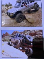
I drove this thing until the former bottomed out (oops)….
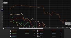
Would port size issues and turbulence show up in a way I could recognize it with this measurement(s)?
Would port size issues and turbulence show up in a way I could recognize it with this measurement(s)?
Attachments

Last edited:

Tapered pipe from ~2 x Sd to 1/2 Sd at the exit
(Thx to my boyfriend @maxolini for the cad drawing)😝
(Thx to my boyfriend @maxolini for the cad drawing)😝
Attachments
Not sure where the TQWT in the title comes. No Port. No TQWP.
And what does Sd have to do with anything.
dave
And what does Sd have to do with anything.
dave
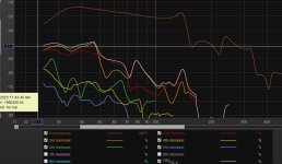
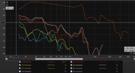
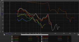
Turbulence might show up as THD in a measurement....Compression will show as a change in the FR/GDWould port compression and turbulence show up in a way I could recognize it with this measurement(s)?
Can you show the multiple GD?
You are a genius at folding I see.
A simple test for turbulent port flow:
https://www.diyaudio.com/community/...rbers-and-port-geometries.388264/post-7436529
RTA turbulent chuffing measurement:
https://www.diyaudio.com/community/...rbers-and-port-geometries.388264/post-7503431
More RTA chuffing measurements of different ports:
https://www.diyaudio.com/community/...rbers-and-port-geometries.388264/post-7695346
You can also see turbulent port flow in impedance measurements done with increasing voltage levels (take good care of the measurement resisor!). The "tuning" will get higher once the laminar flow is disrupted:
https://www.diyaudio.com/community/...rbers-and-port-geometries.388264/post-7534826
Edit: fixed the URLs!
Last edited:
Links don’t work @stv


Turbulence might show up as THD in a measurement....Compression will show as a change in the FR/GD
Can you show the multiple GD?
You are a genius at folding I see.
Sorry about that - fixed them!Links don’t work @stv
a big nope lol... It looks like... as the measurement gets louder, Direct sounds dominates the measurement more for whatever reason, the hair leaves the FR and the GD lowers since you are getting less of the room in the measurement when it was loud. Also, take with a grain of salt as with most measurement predictions lol
This is super intersting!A simple test for turbulent port flow:
https://www.diyaudio.com/community/...rbers-and-port-geometries.388264/post-7436529
RTA turbulent chuffing measurement:
https://www.diyaudio.com/community/...rbers-and-port-geometries.388264/post-7503431
More RTA chuffing measurements of different ports:
https://www.diyaudio.com/community/...rbers-and-port-geometries.388264/post-7695346
You can also see turbulent port flow in impedance measurements done with increasing voltage levels (take good care of the measurement resisor!). The "tuning" will get higher once the laminar flow is disrupted:
https://www.diyaudio.com/community/...rbers-and-port-geometries.388264/post-7534826
Edit: fixed the URLs!
Attachments
Not sure where the TQWT in the title comes. No Port. No TQWP.
TQWT or TQWP = TAPPED Quarter Wave Tube or Pipe = Straight Flare TH.
Max's model is a single fold T-TQWT or T-TQWP = TAPERED-TAPPED Quarter Wave Tube or Pipe = Negative Flare TH.
This enclosure is a double fold T-TQWT.
This is super interesting!
Basically why brass instruments and Balance Of Performance (BOP) air intake restrictors have similar exits!
It's junk and worthless to YOU because it's confusing to YOU.That naming junk is so old and worthless…. Confusing….
They are all 1/4 wave resonators with various shapes that create more/less high frequency junk that limits the bandwidth.
Tqwrtlgbt doesn’t really help describe much ?
True, they are all QWR's. However, the mounting position of the driver and the flare rate changes the enclosure type.
Mount a driver on the outside of a Tapped Horn, then you have a Transmission Line. You went from a 6th order to a 4th order enclosure. We already discussed what happens when you swap the throat and mouth of a TH. You go from an efficient and big enclosure to a low and small enclosure...Hofmann's Iron Law.
BTW, bjorno named the negative flare TH, T-TQWT. Bjorno was a modeling BEAST on diyaudio.
Whoa??? What’s that cheater ‘port’ for a 2jz or 7mtge??
Attachments
Last edited:
- Home
- Loudspeakers
- Subwoofers
- Port compression in TQWPipe?